
Magnetic confinement of a plasma

a plasma and magnetic confinement technology, applied in the direction of plasma technique, spraying apparatus, coating, etc., can solve the problems of increased substrate defects, degrading process performance, and unsatisfactory plasma constituent contact with other components,

Inactive Publication Date: 2012-01-10
APPLIED MATERIALS INC
View PDF8 Cites 34 Cited by
  • Summary
  • Abstract
  • Description
  • Claims
  • Application Information

AI Technical Summary

Problems solved by technology

Although the constituents of the plasma are beneficial for assisting or carrying out the process on the substrate, it is often undesirable for the plasma constituents to come into contact with other components within the process chamber, such as the substrate support, sidewalls, or lid of the chamber.
However, these baffles transfer the problem from one of the plasma contamination or attack of the process chamber to plasma attack or contamination of the baffles themselves.
As such, the baffles become a consumable material that may contribute to particulate defects on the substrate and further require periodic maintenance or replacement.
In addition, physical confinement of the plasma using baffles restricts the ability to pump out plasma effluent from the chamber, thereby further degrading process performance and potentially leading to substandard process throughput and increased substrate defects.

Method used


Image

  • Magnetic confinement of a plasma
  • Magnetic confinement of a plasma
  • Magnetic confinement of a plasma

Examples


Embodiment Construction

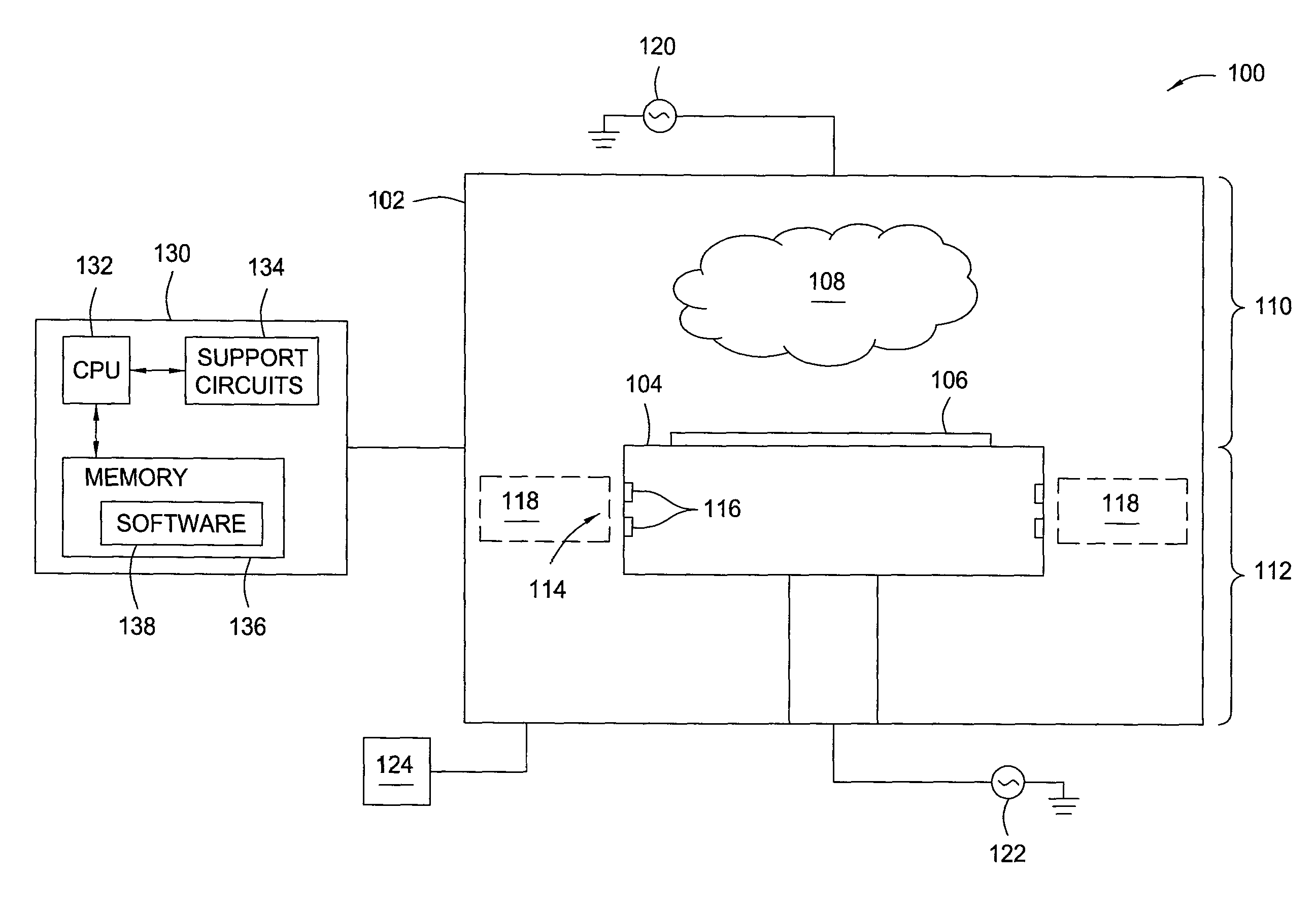
[0018]The present invention provides methods and apparatus for confining a plasma using a magnetic field. In addition, the present invention further contemplates providing a method and apparatus for process selective plasma confinement using a magnetic field. In one embodiment, the method and apparatus of the invention confines a plasma discharge by exposing the plasma periphery to a magnetic field with a component perpendicular to the direction of desired confinement. The strength, direction, and location of the field is selected such that it confines plasmas under a first subset of process conditions, and does not confine plasmas under a second subset of process conditions that differs from the first subset.

[0019]FIG. 1 schematically depicts a chamber 100 having a plasma confinement apparatus in accordance with the present invention. The chamber 100 may generally be any type of process chamber suitable for forming a plasma as modified by the teachings disclosed herein, including, ...


PUM

PropertyMeasurementUnit
frequencyaaaaaaaaaa
bias poweraaaaaaaaaa
magnetic fieldaaaaaaaaaa

Abstract

A method and apparatus for confining a plasma are provided herein. In one embodiment, an apparatus for confining a plasma includes a substrate support and a magnetic field forming device for forming a magnetic field proximate a boundary between a first region disposed at least above the substrate support, where a plasma is to be formed, and a second region, where the plasma is to be selectively restricted. The magnetic field has b-field components perpendicular to a direction of desired plasma confinement that selectively restrict movement of charged species of the plasma from the first region to the second region dependent upon the process conditions used to form the plasma.

Description

BACKGROUND OF THE INVENTION[0001]1. Field of the Invention[0002]Embodiments of the present invention generally relate to plasma-assisted processing of substrates, and more particularly, to magnetic confinement of a plasma in plasma-assisted substrate processing chamber.[0003]2. Description of the Related Art[0004]Plasma-assisted processing is a technique commonly used, for example, in the manufacture of semiconductor devices and integrated circuits. Such processing generally includes introducing a process gas into a chamber having a substrate, such as a semiconductor wafer, disposed therein and applying sufficient energy to the process gas to form a plasma over the substrate. The plasma contains dissociated and ionized components as well as neutral components that operate to assist the process being performed on the substrate (such as deposition, etching, and the like). Although the constituents of the plasma are beneficial for assisting or carrying out the process on the substrate,...

Claims


Application Information

Patent Timeline
Patent Type & Authority Patents(United States)
IPC IPC(8): C23C16/00H01L21/306C23F1/00
CPCH01J37/32082H01J37/32623H01J37/3266H05H1/24H05H1/30H05H1/40
Inventor SHANNON, STEVEN C.DREXEL, MASAOSTINNETT, JAMES A.RUI, YINGXIAO, YINGLINDLEY, ROGER A.YOUSIF, IMAD
Owner APPLIED MATERIALS INC
Learn More