
Fuel pump for internal combustion engine

a fuel pump and internal combustion engine technology, applied in the direction of machines/engines, liquid fuel engines, positive displacement liquid engines, etc., can solve the problems of fuel leakage, increased loss of driving power of the pump, and limitation of the passage area of the clearance, so as to restrict the loss of driving power

Inactive Publication Date: 2012-01-10
DENSO CORP
View PDF17 Cites 2 Cited by
  • Summary
  • Abstract
  • Description
  • Claims
  • Application Information

AI Technical Summary

Benefits of technology

The present invention aims to produce a fuel pump that can prevent the loss of power caused by returning fuel. The fuel pump has a compression chamber and a plunger that pressurizes fuel. It also has a discharge valve that opens when pressure in the chamber reaches a certain level. The pump has a fuel passage with an in-passage member that acts as a throttle to restrict fuel returning from the engine. This results in improved fuel efficiency and power output.

Problems solved by technology

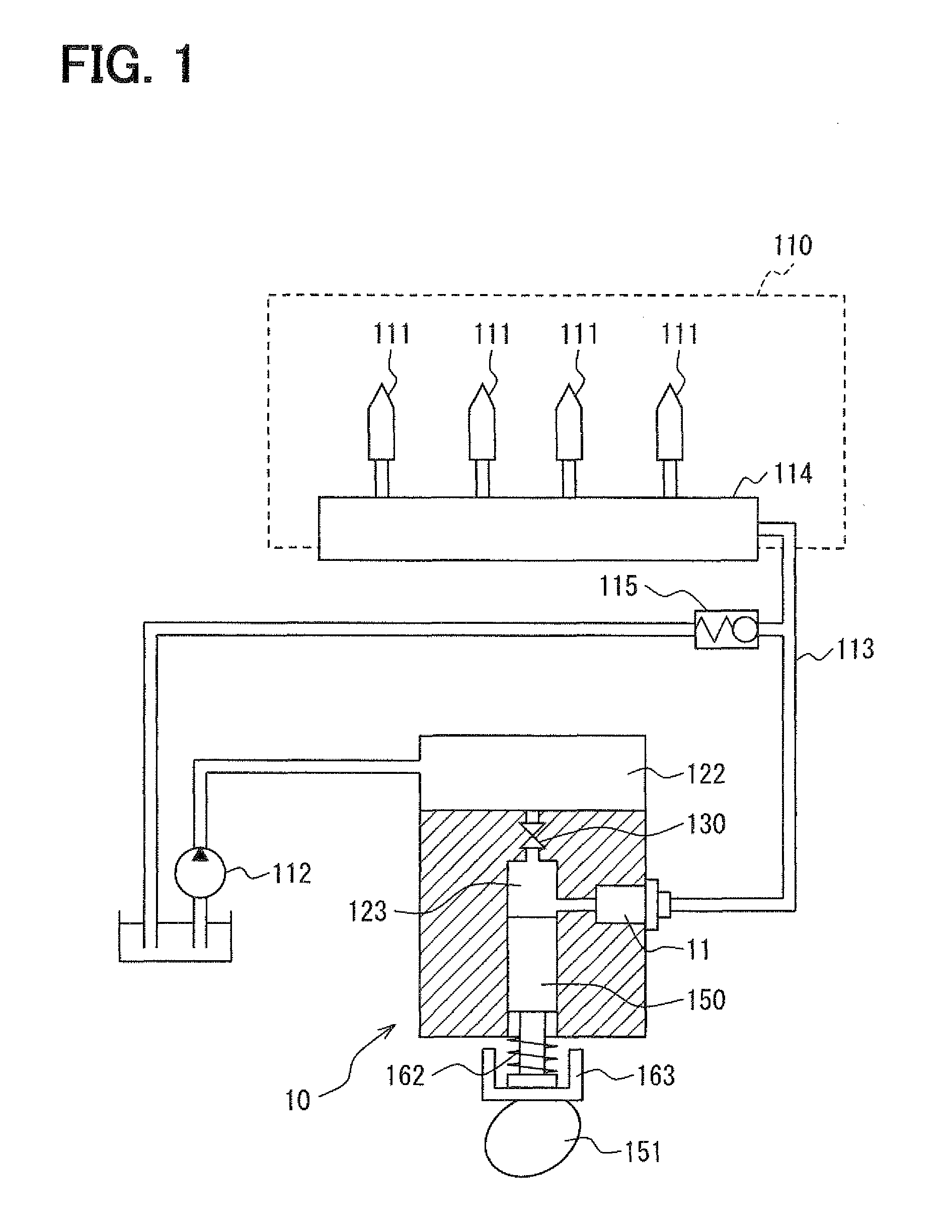
Accordingly, fuel may leak from a valve portion of the fuel injection valve into the combustion chamber of the internal combustion engine, which is being stopped.
However, when fuel pressure in the upstream of the fuel injection valve is high, a large amount of fuel is injected from the fuel injection valve at the time of resuming the fuel injection.
As a result, loss in driving power of the pump increases.
Accordingly, the present structure, in which fuel returns from the downstream of the high-pressure fuel pump to the low-pressure component by utilizing the clearance between the outer wall of the housing of the discharge valve or the relief valve and the mount hole, has a limitation in reduction in passage area of the clearance.
That is, it is difficult to significantly reduce the amount of fuel returning to the low-pressure component.

Method used


Image

  • Fuel pump for internal combustion engine
  • Fuel pump for internal combustion engine
  • Fuel pump for internal combustion engine

Examples


first embodiment

Modification of First Embodiment

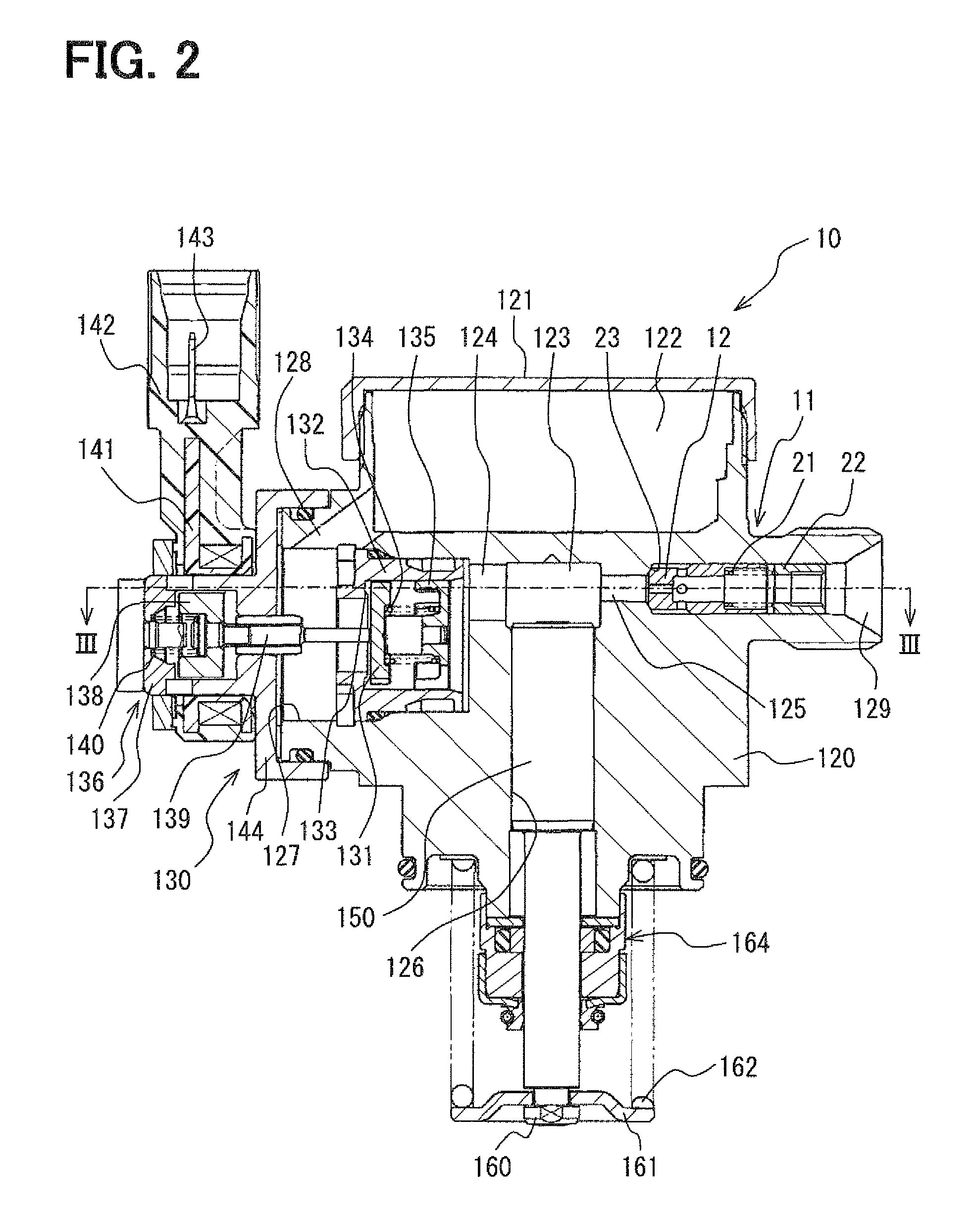
[0085]As shown in FIG. 7, according to the modification of the first embodiment, a ball valve 31 as a valve element is provided for opening and closing a discharge valve 30. The ball valve 31 is fixed with a cylindrical member 32 by welding or the like. The cylindrical member 32 has the outlet portion 129, which is provided with a stopper 33. The stopper 33 has a fuel passage therein. The stopper 33 is supported by the inner wall of the discharge passage 125.

[0086]A cylindrical member 34 is provided to the end of the stopper 33 at the side of the compression chamber 123. The cylindrical member 34 supports the inner wall of the cylindrical member 32, thereby to axially guide the movement of the cylindrical member 32. The outer wall of the cylindrical member 34 has a groove portion 35. The groove portion 35 communicates a space, which is surrounded by the cylindrical member 32, the ball valve 31, and the cylindrical member 34, with the discharge passage...

second embodiment

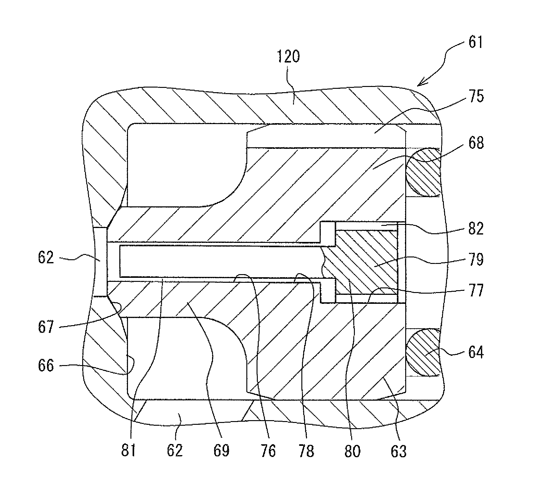
[0090]According to the present embodiment shown in FIGS. 8, 9, a clearance is defined by shifting the center axis of a hole in a component. That is, the structure of the present second embodiment is dissimilar to the structure in the first embodiment, in which the clearance 20 is defined between the inner wall of the passage 14 and the outer wall of the pin 17, which is accommodated in the passage 14. Also in the present embodiment, multiple members are combined to define a device, which is equivalent to the throttle portion.

[0091]As shown in FIG. 8, a passage 42 is provided in the bottom portion of a valve element 41. The passage 42 has a large-diameter passage portion 43 and a small-diameter passage portion 44. The large-diameter passage portion 43 accommodates three sheet members 45. The three sheet members 45 are stacked such that the axial direction of the passage 42 substantially coincides with the thickness direction of each sheet member 45. The three sheet members 45 are equ...

third embodiment

[0098]According to the first and second embodiments, the fuel returning to the upstream of the discharge valve 11, 30, 40 is decreased by reducing the clearance 20 and the diameter of the throttle hole 47. In the present embodiment shown in FIG. 10, the fuel returning to the upstream of a discharge valve 50 is significantly decreased by enhancing flow resistance. Also in the present embodiment, multiple members are combined to define a device, which is equivalent to the throttle portion.

[0099]As shown in FIG. 10, a passage 52 is provided in the bottom portion of a valve element 51. The passage 52 has a large-diameter passage portion 53 and a small-diameter passage portion 54. The large-diameter passage portion 53 accommodates three cup members 55, which are stacked in piles and each being in a cup-shape. The three cup members 55 are equivalent to an in-passage member and a cup member. The valve element 51 accommodates the three cup members 55. The valve element 51 has the passage 52...


PUM


Abstract

A fuel pump includes a pump housing having a compression chamber. A plunger is axially movable in the pump housing for pressurizing fuel in the compression chamber. A discharge valve is configured to open to supply fuel from the compression chamber to an internal combustion engine when pressure in the compression chamber is more than predetermined pressure. A fuel passage is configured to communicate a downstream of the discharge valve with an upstream of the discharge valve. An in-passage member is accommodated in the fuel passage. The in-passage member includes multiple members, which are combined to define a throttle portion for restricting fuel, which returns from the downstream of the discharge valve to the upstream of the discharge valve.

Description

CROSS REFERENCE TO RELATED APPLICATIONS[0001]This application is based on and incorporates herein by reference Japanese Patent Application No. 2007-178904 filed on Jul. 6, 2007.FIELD OF THE INVENTION[0002]The present invention relates to a fuel pump having a plunger for pressurizing fuel in a compression chamber to supply the fuel to an internal combustion engine.BACKGROUND OF THE INVENTION[0003]For example, US 2006 / 0222538 A1 (JP-A-2006-307829) discloses a high-pressure fuel pump having a plunger for pressurizing fuel in a compression chamber and supplying the fuel to an internal combustion engine. The fuel supplied to the internal combustion engine is injected from a fuel injection valve into a combustion chamber. The high-pressure fuel pump is provided with a discharge valve. The discharge valve is provided at the downstream of a compression chamber. The discharge valve opens to supply fuel from the compression chamber to the internal combustion engine when fuel pressure in the c...

Claims


Application Information

Patent Timeline
Patent Type & Authority Patents(United States)
IPC IPC(8): F04B53/10
CPCF02M59/447F02M59/462Y10T137/7849Y10T137/7847
Inventor KOBAYASHI, MASAYUKISHIBATA, HITOSHIOGURI, TATSUMI
Owner DENSO CORP
Learn More