
Electromagnetic waveguide

Pending Publication Date: 2022-08-04
UNIV DE LIMO +1
View PDF0 Cites 0 Cited by
  • Summary
  • Abstract
  • Description
  • Claims
  • Application Information

AI Technical Summary

Benefits of technology

The patent text discusses a way to reduce the losses of a waveguide by using a certain ratio between the area of the central hollow portion and the area of the at least one hollow secondary tube. The technical effect is to improve the performance of the waveguide by reducing its losses.

Problems solved by technology

This type of fibres nevertheless has limitations, in particular in terms of:a. linear losses: these reach approximately 1 dB / km for a wavelength of the order of 1.5 μm, this value increasing rapidly for shorter wavelengths such as those in the visible domain, for which linear losses of the order of 1000 dB / km may be reached;b. lag for high-power lasers: as a result of a significant overlap of the guided mode in the core of the fibre with its silica contour; the damage threshold exhibited is only slightly higher than for solid-core fibres of the same diameter;c. bandwidth: the hollow PFB fibres have a narrow transmission band, of the order of 70 THz.
These transmission bands are too narrow for applications such as non-linear optics, frequency conversion, very short laser pulses;d. dispersion: despite guiding in air, dispersion in the hollow PFB fibres is too high and structured, which poses a problem for applications such as high-resolution spectroscopy or for short laser pulses, and also limits single-mode guiding in this type of fibre.
In addition, as the current optical fibres are intrinsically multimode, this limits their application in certain fields such as telecommunications, for example.

Method used


Image

  • Electromagnetic waveguide
  • Electromagnetic waveguide
  • Electromagnetic waveguide

Examples


Embodiment Construction

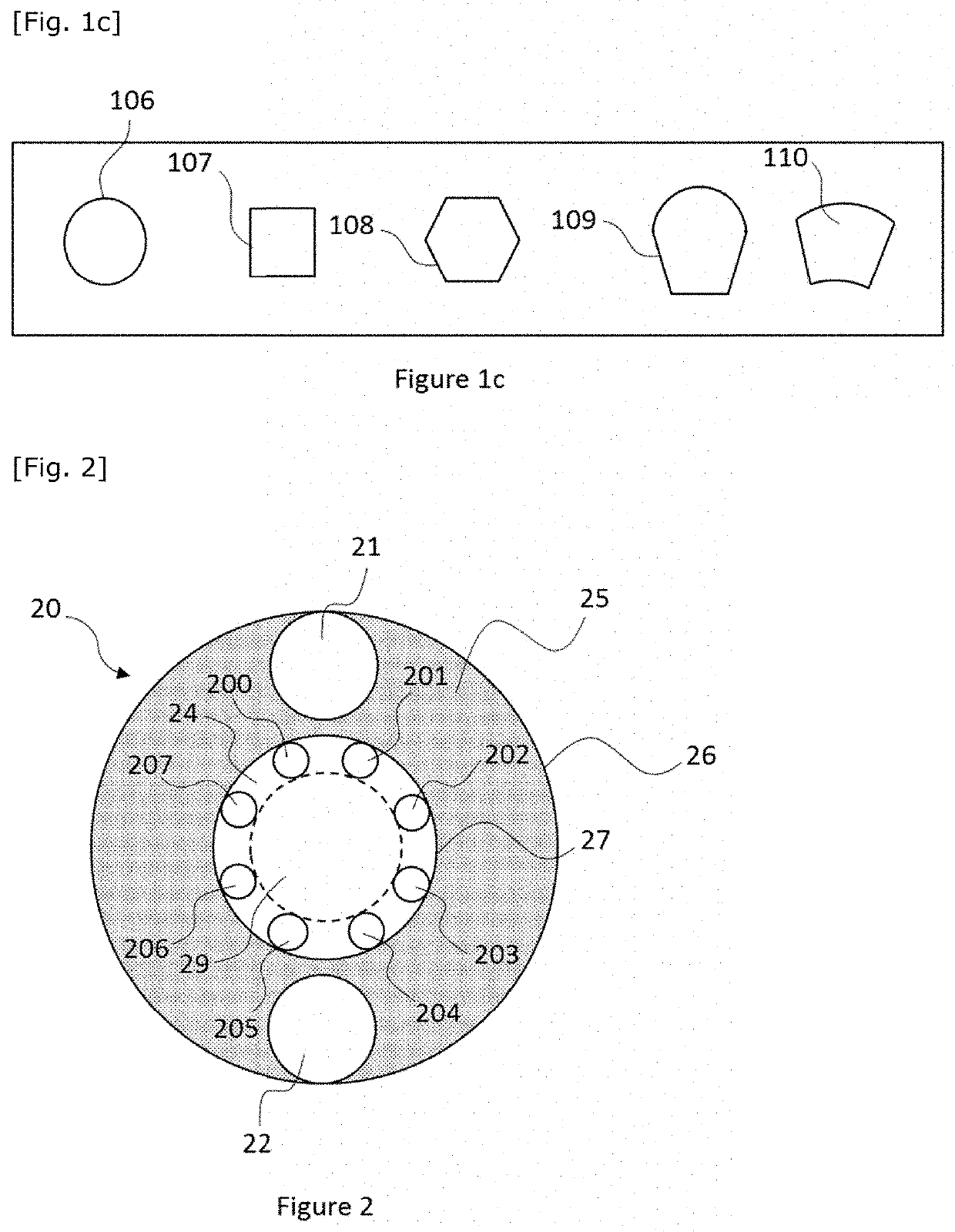
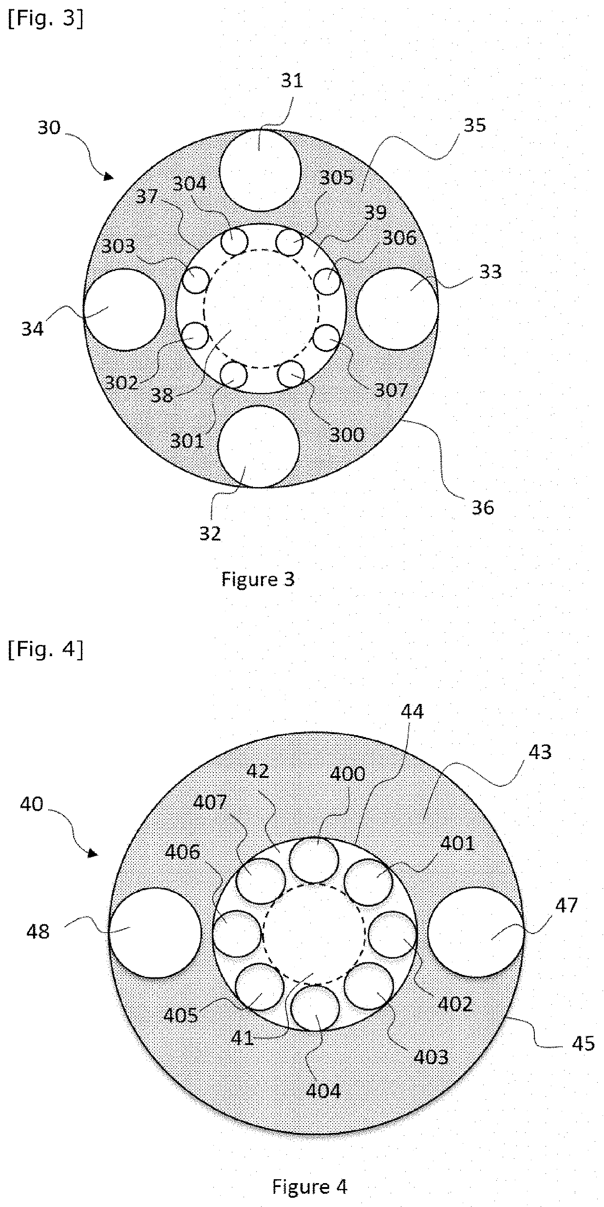
[0091]The purpose of the present invention is in particular to propose an electromagnetic waveguide having a hollow central portion delimited by a first set of tubes isolated from one another, borne by a first tubular structure, and ordered so as to form a ring, for example called inner ring or first ring, and a second annular structure or outer ring. The second annular structure can advantageously comprise a second set of tubes positioned around the ring formed by the tubes of the inner ring.

[0092]The present invention can be applied in different fields, in particular for guiding waves in the optical, terahertz and microwave domains

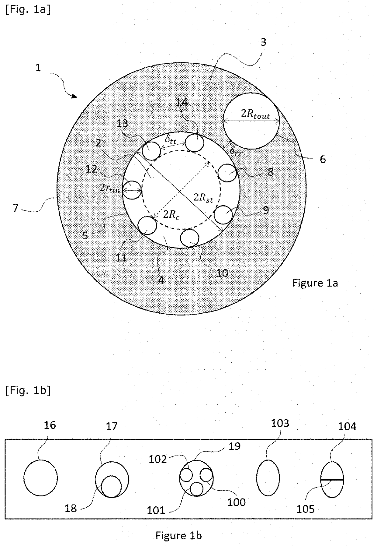
[0093]FIG. 1a shows a first example of an electromagnetic waveguide 1 according to the invention. The first electromagnetic waveguide 1 can be a hollow optical fibre guiding by inhibited coupling.

[0094]The waveguide 1 comprises a hollow central portion or hollow core 2 that can either be filled with air, or with an inert gas, or can even be a void. The h...


PUM


Abstract

A field of waveguides is disclosed. A tubular electromagnetic waveguide includes a hollow central portion defined by a first set of at least seven primary hollow tubes that are distributed annually about the hollow central portion, and a second set of tubes including at least one secondary hollow tube; when there are a plurality thereof positioned annularly around the primary hollow tubes the area of the at least one secondary hollow tube is comprised between 0.35 and 0.50 times the area of the hollow central portion. The hollow tubes of the first set are substantially of same size and distant from one another.

Description

TECHNICAL FIELD[0001]The present invention relates to the field of electromagnetic waveguiding, in particular by the inhibited-coupling mechanism and in particular waves in the optical, terahertz and microwave domains.[0002]The invention proposes a waveguide allowing single-mode guiding, and in some cases, preservation of the polarization of the electromagnetic wave in the waveguide.STATE OF THE ART[0003]Several types of hollow optical fibres are currently used or are the subject of research.[0004]Among these types of optical fibres there are hollow-core photonic crystal fibres or hollow micro structured fibres, using Photonic Forbidden Band guidance, also known as PFB. Such fibres are beneficial in the fields of non-linear optics, conversion of optical frequencies, and spectroscopy. This type of fibres nevertheless has limitations, in particular in terms of:[0005]a. linear losses: these reach approximately 1 dB / km for a wavelength of the order of 1.5 μm, this value increasing rapid...

Claims


Application Information

Patent Timeline
IPC IPC(8): G02B6/02G02B6/024H01P3/12
CPCG02B6/02328H01P3/12G02B6/024G02B6/02366G02B6/02361H01P3/127
Inventor BENABID, FETAHVINCETTI, LUCAGIOVANARDI, FABIO
Owner UNIV DE LIMO
Learn More