Device for fixing conductor tracks on a solar cell

a solar cell and track technology, applied in the direction of gas flame welding apparatus, non-electric welding apparatus, auxiliary devices for welding, etc., can solve the problems of difficult to bring into the desired surface contact (fixation) with the upper surface, the construction of the hold-down device is complex, and the conductor track can easily be damaged, etc., to achieve optimized (steady) transport and high clock rate

Inactive Publication Date: 2012-01-10
KIOTO PHOTOVOLTAICS
View PDF16 Cites 0 Cited by
  • Summary
  • Abstract
  • Description
  • Claims
  • Application Information

AI Technical Summary

Benefits of technology

[0018]The springs ensure a soft contact between the hold-down device and the conductor track. The springs also make it possible to apply an even pressure by the hold-down devices onto the conductor track. The springs have the further advantages that—within certain limits—the compressive forces the hold-down devices exert onto the conductor tracks vary insignificantly even though there are different distances between crossbar and solar cell. The planar design of the contact ends of the hold-down device homogenises the pressure distribution exerted by the hold-down devices onto the conductor tracks (solar cells). This is achieved by spherical bodies at the free end of the hold-down devices that leave distinctive calotte-like (spherical) indentations in a subsequent soldering process during which the conductor tracks become viscous at least in the surface area. Again during the soldering process when the spherical bodies are pressed into the surface of the conductor track the optimized pressure distribution of the hold-down devices is maintained and significantly improved with respect to the state of the art. “Calotte-like” according to the invention means that an indentation is no unidirectional indentation (in the technical sense), as obtained by a needle according to the state of the art, but describes an indentation in the conductor track that extends over a certain surface area of the conductor track.
[0027]The pushing of the conductor track onto the solar cell can additionally be improved if a hold-down device with a spherical body is used, that has a profiled (textured) surface forming an indentation that has a correspondingly structured (textured) surface, for example a latticed wall section.
[0028]In this embodiment various compression forces of different pressure directions are submitted (transmitted) by the hold-down device onto the conductor track and from the conductor track onto the solar cell so that the solder connection during the subsequent soldering process is sustainably improved, in particular a substantially higher surface contact between conductor track and solar cell is achieved, which is important for the electrical conduction.
[0034]The speed by which the crossbar is moved from the staring position into the operating position can be degressive, that means decreasing towards the end to prevent that the hold-down devices shift the conductor tracks if there is not a 100% alignment of crossbar and solar cells.
[0035]The transport installation can include at least one product carrier on which the solar cells (or a solar cell-string) lie. The carriers can have bridge-like ridges on their surface pointing towards the solar cells that are arranged in such a manner that the conductor tracks which run along the second main-surface of the solar cells are supported by the bridge-like ridges and extend parallel to them. This results in an embodiment where the solar cells have planar sections on both sides that are uncovered at least partly. The product carriers are moved by suitable means into the desired position, preferably by a drive. As one product carrier picks up at least one complete solar cell-string a high clock rate is realized and an optimized (steady) transport as well as a steady soldering process in which at least one string is soldered at a time.

Problems solved by technology

This is difficult inter alia because the solar cells are extremely thin (approximately 200 μm) and brittle and the conductor tracks with a width of for example 0.5 to 3 mm and a thickness of not more than 0.2 to 1 mm are thin strips, which cannot be brought easily into the desired surface contact (fixation) with the upper surface / lower surface of the solar cell.
The known hold-down device is constructionally very complex, the pins cause very small pressure-points, whereby the conductor tracks can easily be damaged.
Furthermore, an adjustment of the compressive force with respect to the area of the conductor tracks is impossible and can incidentally only be done individually through the holding-down heads.
As a result the known solar cell-string has no sufficient surface connection between conductor track and solar cell.

Method used


Image

  • Device for fixing conductor tracks on a solar cell
  • Device for fixing conductor tracks on a solar cell
  • Device for fixing conductor tracks on a solar cell

Examples


Embodiment Construction

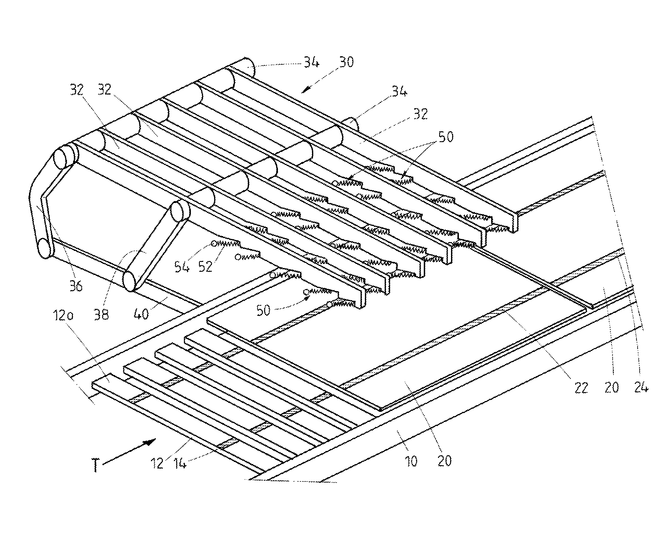
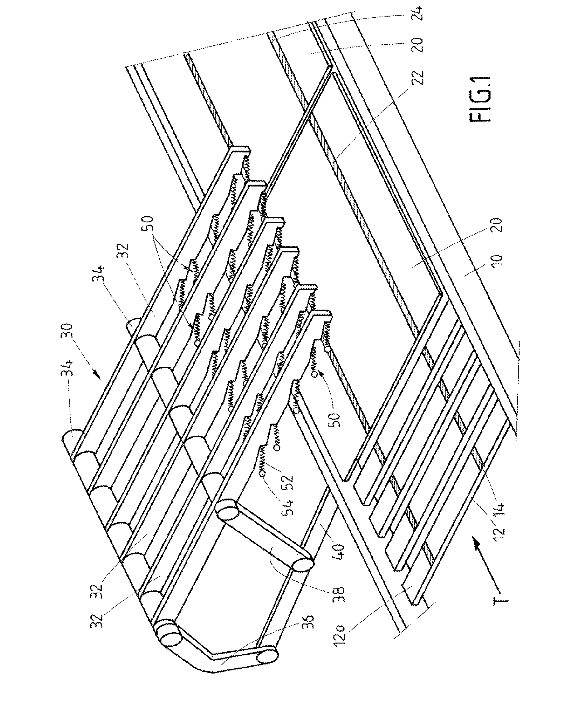
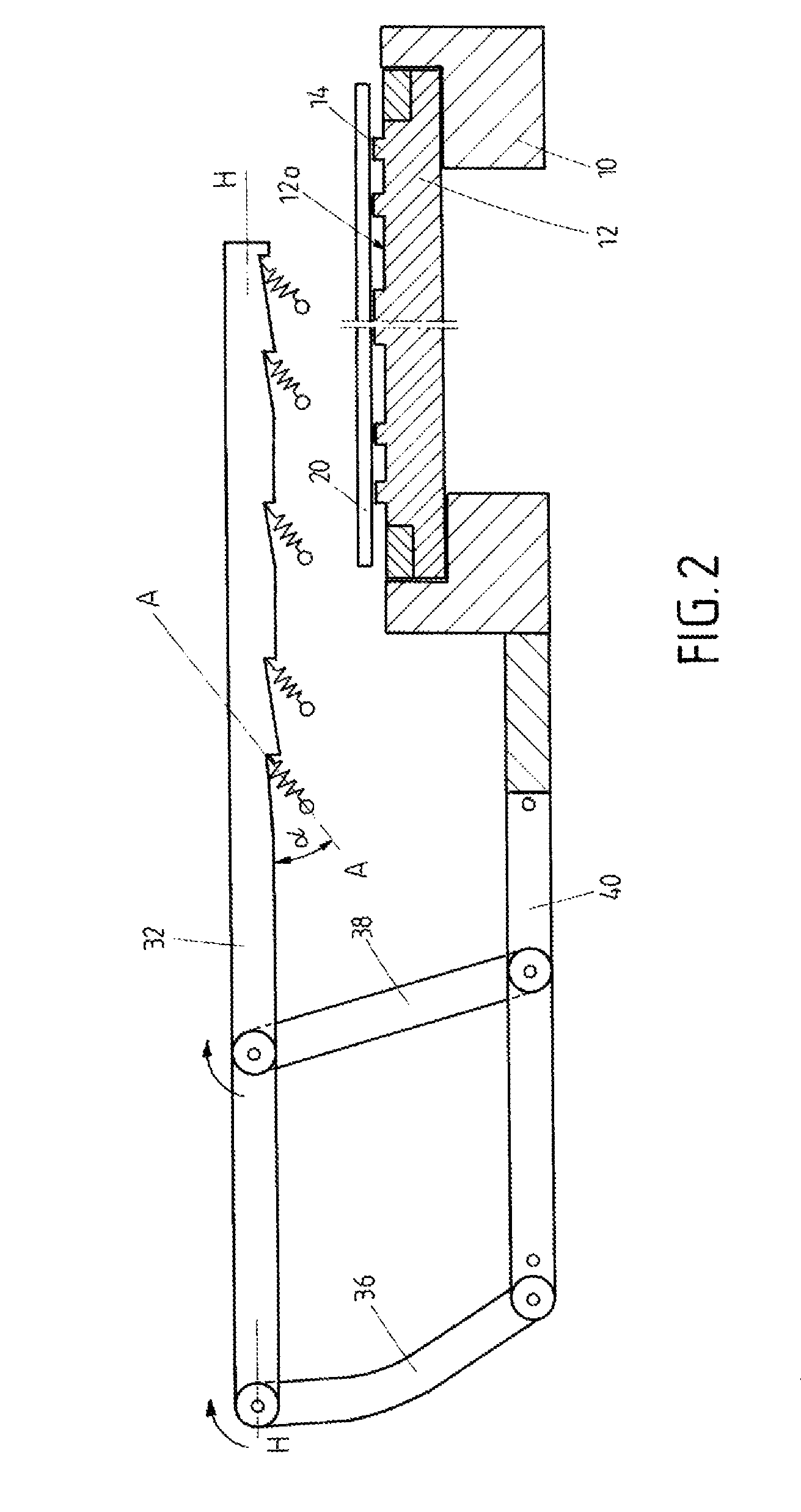
[0044]The device includes a transport system the transport direction of which is characterized by arrow T. The transport system includes transport carriers 10 with tracks 12 that extend perpendicular to the transport direction T. Their upper surface 12o (in the operating position of the device) has bridge-like ridges 14 that extend in transport direction 10, in other words: perpendicular to longitudinal direction of the tracks 12. Several tracks are connected to a transport carrier 10.

[0045]On the tracks 12 solar cells 20 are arranged wherein several solar cells 20 are connected to a solar cell-string by corresponding conductor tracks 22, 24. One transport carrier 10 supports at least one complete string.

[0046]The transport carriers 10 are moved by driving-means not shown.

[0047]The device further comprises a crossbar 30 that has several arms 32 extending parallel at a distance to each other resting pivotably on two cross members 34 that are arranged at a distance to each other where...


PUM

PropertyMeasurementUnit
angleaaaaaaaaaa
angleaaaaaaaaaa
angleaaaaaaaaaa

Abstract

The invention concerns to a device for fixing conductor tracks on at least one first main-surface of at least one solar cell.

Description

FIELD OF THE INVENTION[0001]The invention relates to a device for fixing conductor tracks (conductor strips) on at least one first main-surface of at least one solar cell.BACKGROUND OF THE INVENTION[0002]Usually at least two conductor tracks (conductor paths) extend parallel to each other on a solar cell (photovoltaic-cell), wherein a pair (2) of conductor tracks connect a first main-surface (upper side) of a solar cell with a second main-surface (lower side) of an adjacent solar cell. A series of solar cells connected in this manner form a so called solar cell string, accordingly providing the following features:[0003]this string comprises a series of solar cells arranged in succession,[0004]adjacent solar cells are connected by at least two electrical conductor tracks,[0005]each conductor track is firmly connected with a first section to an upper surface of a solar cell and with a second section to a lower surface of the adjacent solar cell.[0006]Usually the conductor tracks have ...

Claims


Application Information

Patent Timeline
Patent Type & Authority Patents(United States)
IPC IPC(8): B23K37/00
CPCB23K1/0008B23K3/087B23K37/0408B23K2201/40B23K2101/40
Inventor EUSCH, INGRAMFRANK, RUDOLFKOGLER, ARMIN
Owner KIOTO PHOTOVOLTAICS
Why Eureka
Try Eureka