
Method for correcting astigmatism in electron emission spectromicroscopy imaging

a technology of electron emission spectromicroscopy and astigmatism, which is applied in the field of spectromicroscopy imaging, can solve the problems of limiting the resolution of electron emission imaging, over-intensities and under-intensities in the image obtained, and limiting the lateral resolution of peem imaging

Inactive Publication Date: 2012-01-03
COMMISSARIAT A LENERGIE ATOMIQUE ET AUX ENERGIES ALTERNATIVES
View PDF17 Cites 0 Cited by
  • Summary
  • Abstract
  • Description
  • Claims
  • Application Information

AI Technical Summary

Benefits of technology

[0016]eliminating astigmatism defects appearing during the imaging of the reference structure with secondary electrons and with core level photoelectrons,
[0035]The material of the reference structure may be such that the kinetic energy of the core level photoelectrons used for imaging at least one of the constituent elements of said material is less than or equal to around several hundred eV, or less than around 1000 eV. For instance, by choosing a material in which the photoelectrons to be imaged may be excited in such a way that their kinetic energy is low (the kinetic energy depending on the energy of the excitation beam), their transmission by the spectromicroscope is improved, improving the contrast obtained between the material of the reference structure and the material of the sample.

Problems solved by technology

Indeed, if the surface of the sample is rough, these irregularities will disrupt the extraction electric field generated between the sample and the objective, which has the effect of deflecting the path of the photoelectrons emitted, leading to over-intensities and under-intensities in the image obtained.
Spherical and chromatic aberrations, due both to the extraction electric field and to the electrostatic lenses of the objective themselves, are also defects that limit resolution in electron emission imaging.
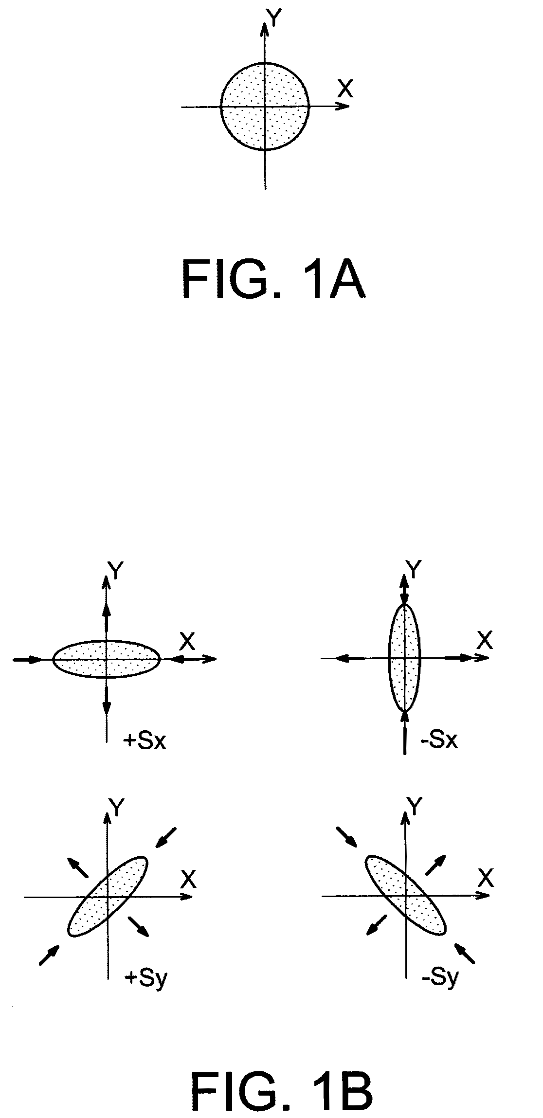
Astigmatism is also a factor that limits lateral resolution in PEEM imaging.
Indeed, the PEEM column does not have a perfect optical axis, these imperfections generally being misalignments between the lenses or instead residual magnetic fields.
The lenses themselves are not perfect either, and often their transmission around the optical axis is not symmetrical.
This astigmatism results in a reduction in the quality of the images obtained (reduction in the lateral resolution, the contrast, etc.), and the correct focusing voltage that needs to be applied is difficult to find.
Such a method nevertheless has the major drawback of not being able to apply in practice for numerous samples because the structures of interest of these samples that it is wished to image generally have a pattern that does not make it possible to clearly highlight the astigmatism defects of the column.
For example, in the case of a sample in which the structure of interest that it is wished to image is composed of horizontal strips, it will be impossible to evaluate and to correct the astigmatism in this horizontal direction parallel to the orientation of the strips of the structure of interest of the sample.

Method used


Image

  • Method for correcting astigmatism in electron emission spectromicroscopy imaging
  • Method for correcting astigmatism in electron emission spectromicroscopy imaging
  • Method for correcting astigmatism in electron emission spectromicroscopy imaging

Examples


Embodiment Construction

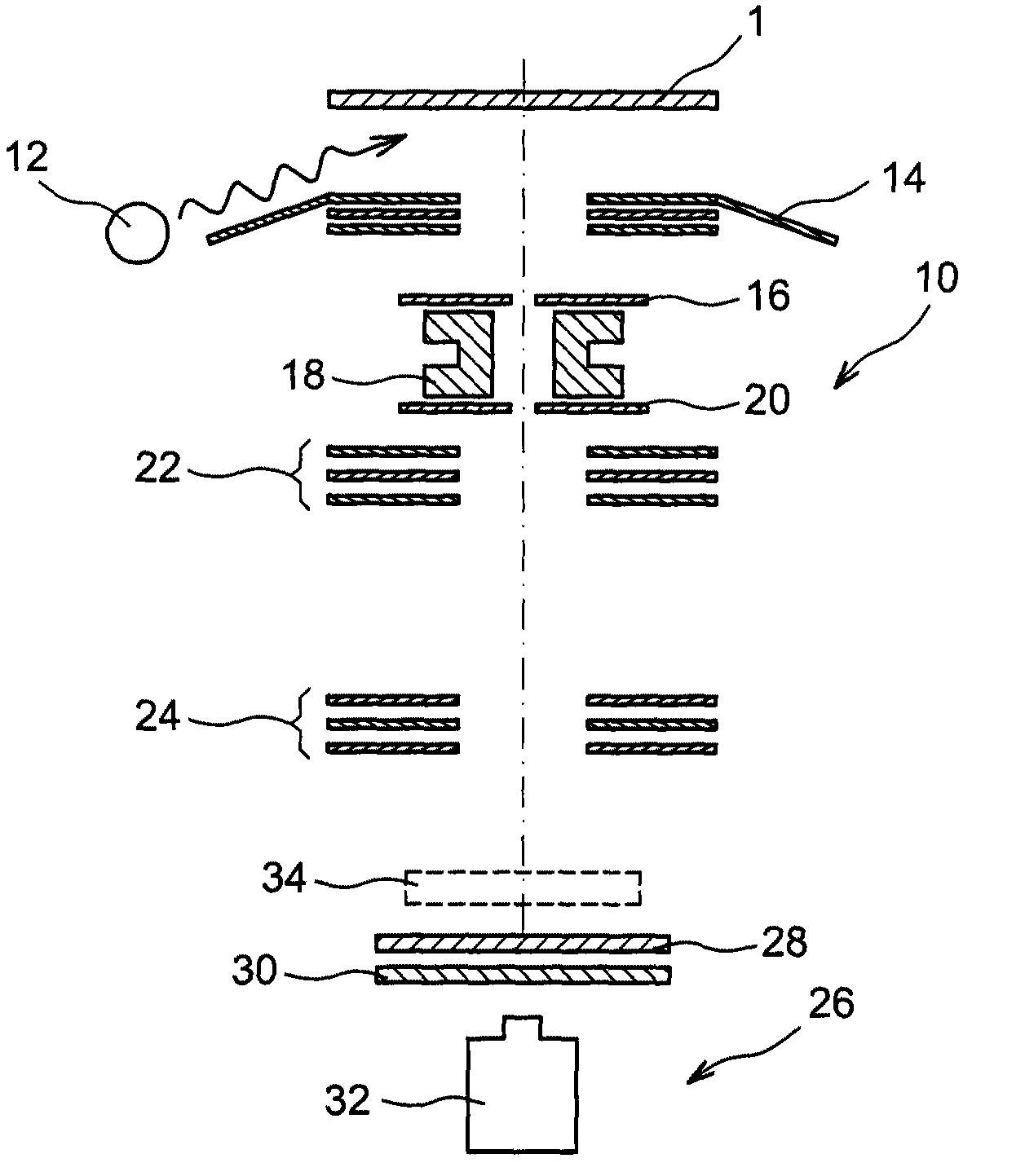
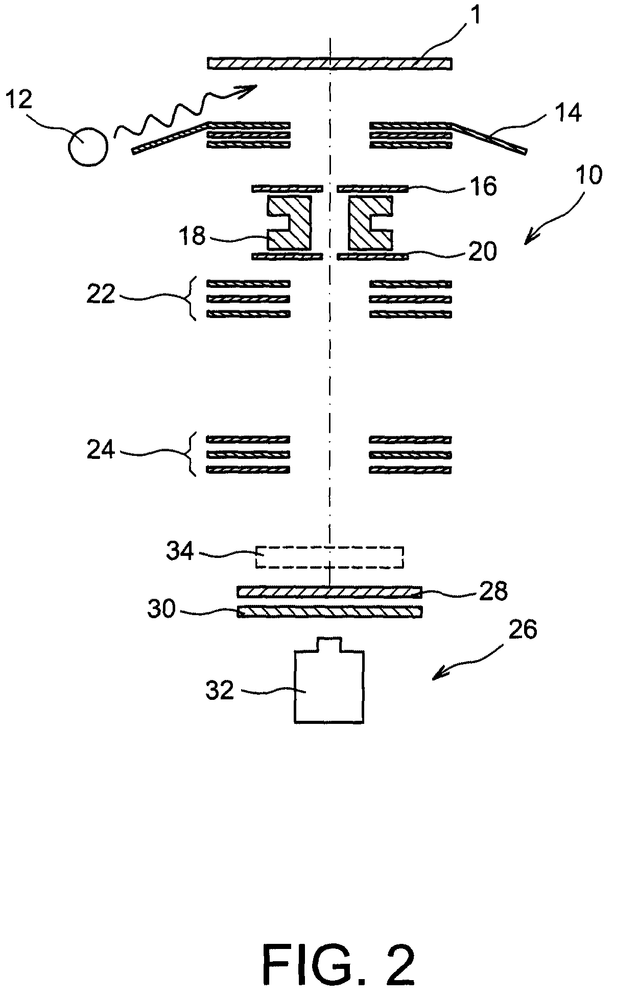
[0012]Thus there is a need to optimise the observation conditions during a method of electron emission spectromicroscopy imaging, for example with photoelectrons, of a structure of interest of a sample by correcting defects of the electronic optical column of a spectromicroscope, and particularly astigmatism.

[0013]To do this, one embodiment proposes a method for correcting astigmatism of an electronic optical column of an electron emission spectromicroscope, comprising at least the steps of:[0014]forming a reference structure on a surface of a sample comprising a structure of interest to be imaged, the dimensions of the exterior contour of the reference structure, along two axes perpendicular to each other and lying in a plane parallel to the surface of the sample, being substantially similar,[0015]imaging the reference structure by the spectromicroscope with secondary electrons and with core level photoelectrons,[0016]eliminating astigmatism defects appearing during the imaging of ...


PUM


Abstract

A method for correcting astigmatism of an electronic optical column of an electron emission spectromicroscope, comprising the steps of:forming a reference structure on a surface of a sample comprising a structure of interest to be imaged,imaging the reference structure by the spectromicroscope with secondary electrons and with core level photoelectrons,eliminating astigmatism defects appearing during the imaging of the reference structure with secondary electrons and with core level photoelectrons,a material of the reference structure being chosen such that, during core level photoelectron imaging, the contrast C between the average intensity Ia of the material of the reference structure and the average intensity Ib of the material of the sample is such that:C=Ia-IbIa+Ib≥0.2.

Description

TECHNICAL FIELD[0001]This document relates to the field of spectromicroscopy imaging, and more specifically that of the correction of defects, particularly astigmatism, of an electronic optical column of an electron emission spectromicroscope, for example with photo-excited electron or photoelectron emission. It particularly applies to the field of full-field XPS (X-ray Photoelectron Spectromicroscopy) imaging.STATE OF THE PRIOR ART[0002]Spectromicroscopy, which combines electron spectroscopy and microscopy, is an imaging technique consisting in irradiating a large surface of a sample to be imaged by a wide beam having a certain energy. When said beam is an X-ray beam, it is known as XPS imaging. This technique uses the principle of the photoelectric effect concerning some of the electrons of the atoms of the material of the sample to be imaged. When a photon interacts with an electron from one of the electron shells of an atom of the sample material, said photon transfers to it its...

Claims


Application Information

Patent Timeline
Patent Type & Authority Patents(United States)
IPC IPC(8): H01J37/00H01J37/153
CPCH01J37/153H01J37/26
Inventor RENAULT, OLIVIERLAVAYSSIERE, MAYLISMARIOLLE, DENIS
Owner COMMISSARIAT A LENERGIE ATOMIQUE ET AUX ENERGIES ALTERNATIVES
Learn More