
Ink storing system and ink delivering system

a technology of ink storage and ink delivery, which is applied in the field of ink storage system and ink delivery system, can solve the problems of air permeating through the walls of ink containers and/or ink delivery passages, forming bubbles, and air having dissolved into ink to form bubbles, etc., and achieves the effect of improving the spatial efficiency of ink storage, and reducing with ink consumption

Inactive Publication Date: 2012-01-03
CANON KK
View PDF23 Cites 15 Cited by
  • Summary
  • Abstract
  • Description
  • Claims
  • Application Information

AI Technical Summary

Benefits of technology

The present invention provides an ink storing system and an ink delivery system that can remove bubbles in the subordinate ink container, even if the power source of the ink jet recording apparatus is on or off, and even if the ink jet recording apparatus is left unattended for a long period of time. This is achieved by using an air-liquid separation device and a negative pressure source in the ink reservoiring portion, which can maintain negative pressure even if the ink reservoiring portion is not in use for a long time. The invention also provides a more efficient and stable ink storage system that reduces the amount of bubbles and the size of the ink storage portion, and reduces the flexing of the flexible sheet, which improves the stability of the ink storage portion in negative pressure.

Problems solved by technology

Because of the structure and / or the properties of the materials for an ink container and an ink delivery passage, it is unavoidable that air permeates through the walls of an ink container and / or ink delivery passage, and forms bubbles in the ink container and / or ink delivery passage.
Further, it sometimes occurs that the changes in the ambient condition cause the air having dissolved into ink to form bubbles by separating from the ink.
However, if bubbles occur in an ink container of the abovementioned type, various problems occur.
For example, if it becomes impossible for an ink container of the above described type to maintain negative pressure because of the expansion of bubbles, ink leaks through the ink outlets of the recording head.
Further, if a bubble is trapped by a filter with which the ink delivery passage is provided, the ink delivery passage is virtually blocked by the trapped bubble, making it impossible for the ink delivery system to satisfactorily deliver ink.
If such a problem occurs, the bubbles in a recording head must be suctioned out or the recording head through the ink outlet.
In the case of the technology disclosed in Japanese Laid-open Patent Application 2005-161770, which is for removing the bubbles in a subordinate ink container, it is unavoidable that the body of ink discharged with the bubbles when the bubbles are removed is wasted.
In other words, this technology increases the operational cost of an ink jet recording apparatus.
Further, this technology requires an absorbent member for absorbing and retaining the discharged ink, being therefore disadvantageous from the standpoint of reducing in size an ink jet recording apparatus.
In the case of the technology disclosed in Japanese Laid-open Patent Application 2005-59491, a certain amount of space is necessary for measuring the amount of the gas with the use of an electrode, being therefore not suitable for reducing in size a subordinate ink container.
In other words, this technology is not promising from the standpoint of spatial efficiency.
Thus, this technology is likely to increase an ink jet recording apparatus in size and cost.
Therefore, this technology is limited in terms of the condition under which a bubble can be removed.
As will be evident from the descriptions of the prior technologies given above, these technologies suffer from their own problems, but, are the same in that a bubble can be removed only when an ink jet recording apparatus is on.
Therefore, if an ink jet recording apparatus is left for a long time without its power source turned on, as it is when an ink jet recording apparatus is kept in a storage, or left unused for a long time, the prior technologies are irrelevant.
Therefore, these technologies all tolerate the bubbles which generate in a subordinate ink container, and therefore, require a subordinate ink container to be larger in size than necessary for a preset amount of ink alone, making it difficult to realize a subordinate ink container which is significantly smaller in size than a subordinate ink container presently available.
Therefore, the effect of the compatibility between the material for a subordinate ink container and the ink therein upon the performance of an ink jet recording apparatus (head) increases, limiting therefore the number of the substances selectable as the material for a subordinate ink container.
Further, increasing a subordinate ink container in storage size is undesirable from the standpoint of the weight reduction of a subordinate ink container (it increases a subordinate ink container in weight).

Method used


Image

  • Ink storing system and ink delivering system
  • Ink storing system and ink delivering system
  • Ink storing system and ink delivering system

Examples


embodiment 1

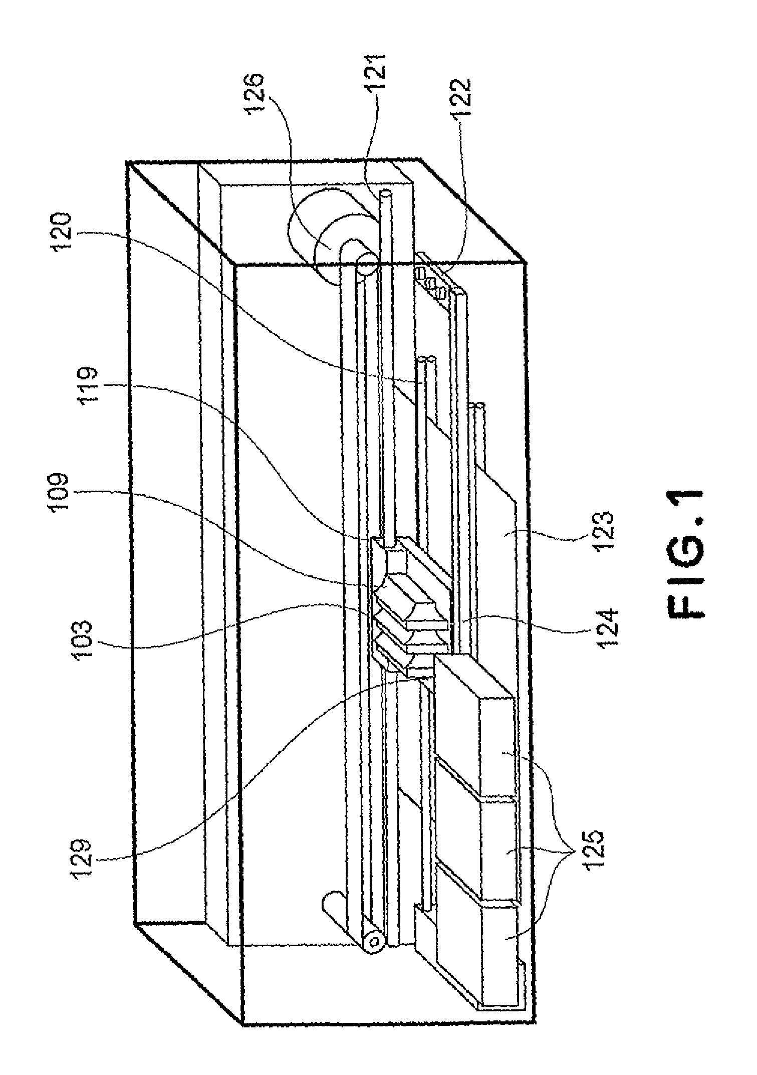
[0033]First, referring to FIG. 1 the general structure of the ink jet recording apparatus in the first embodiment of the present invention will be described.

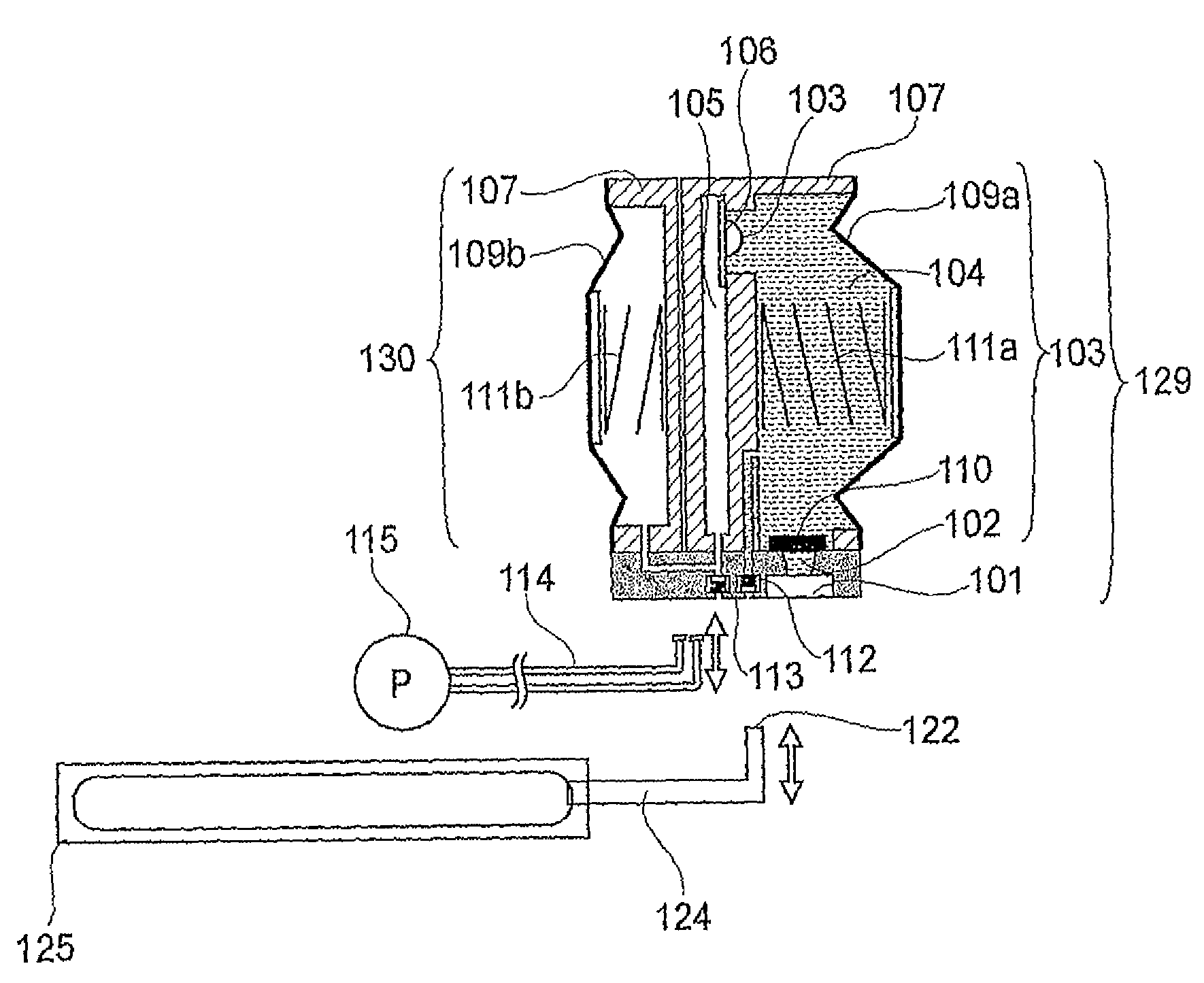
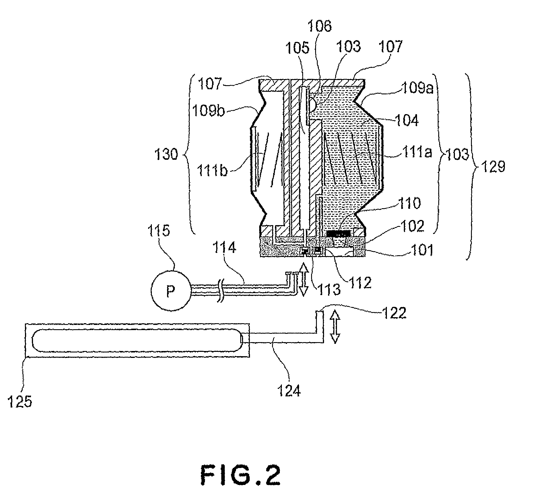
[0034]The ink jet recording apparatus in this embodiment of the present invention has a recording head (unshown), an ink supply source 125 as a main ink container, a subordinate ink container 103 (ink storage portion), and a carriage 119. It is structured so that the subordinate ink container 103 is mounted on the carriage 119, whereas the ink supply source 125 is located off the carriage 119. Thus, the ink jet recording apparatus is provided with an ink delivery tube 124 for guiding the ink in the main container 125 to a preset location, and a connective portion 122, by which the ink delivery tube 124 is connected to the subordinate ink container 103 in order to deliver the ink to the subordinate ink container 103. The ink jet recording apparatus is structured so that as the carriage 119 is moved to a home position or a preset ...

embodiment 2

[0053]FIGS. 8(a)-8(c) are schematic sectional views of the recording head cartridge and gas purging unit in the second embodiment of the present invention.

[0054]The ink container 103 in this embodiment is the same in structure as that in the first embodiment. However, the negative pressure storing portion 130 in this embodiment is different from that in the first embodiment, in that it is a part of the main assembly of an ink jet recording apparatus.

[0055]This negative pressure storing portion 130 is connected to a connective tube 114 (gas passage) which is in connection with the suction pump 115. In terms of the lengthwise direction of the connective tube 114, the negative pressure storing portion 130 is positioned near the home position the recording head unit, and serves as a gas purging unit 116. The gas purging unit 116 is connectible with the air outlet 113 of the ink container 103. When the ink jet recording apparatus is not recording, for example, while it is on standby, mor...

embodiment 3

[0061]FIGS. 10(a)-10(c) are schematic sectional views of the recording head cartridge and gas purging unit in the third embodiment of the present invention.

[0062]The ink container 103 in this embodiment is the same in structure as those in the first and second embodiments. However, the negative pressure storing portion 130 in this embodiment is different from that in the first embodiment, in that it is a part of the main assembly of an ink jet recording apparatus as it is in the second embodiment.

[0063]That is, the negative pressure storing portion 130 in this embodiment is connected to the connective tube 114 which is in connection with the suction pump 115. In terms of the lengthwise direction of the passage 114, the negative pressure storing portion 130 is positioned near the home position of the recording head unit 129, and serves as a gas purging unit 116.

[0064]The gas purging unit 116 is connectable with the air outlet 113 of the ink container 103. When the ink jet recording a...


PUM


Abstract

An ink reservoir mechanism includes a ink reservioring portion for directly reservoiring ink to be supplied to an ink jet recording head, the ink reservoiring portion having a reservoiring volume which reduces with consumption of the ink and being provided with an air-liquid separation device; a negative pressure source, having a variable inner volume, for normally applying a negative pressure to the ink reservoiring portion through the air-liquid separation device; and a connection path for connecting the negative pressure source and the ink reservoiring portion through the air-liquid separation device.

Description

TECHNICAL FIELD[0001]The present invention relates to an ink storing system equipped with an ink storage portion for storing the ink supplied from a main ink container to an ink jet recording head, which forms letters and / or pictorial images on recording medium by jetting liquid from liquid outlets, and an ink delivering system for supplying the ink jet recording head with the ink delivered from the main ink container. In particular, it relates to a combination of an ink storing system and an ink delivering system, which is equipped with a mechanism for purging the ink storage portion of the bubbles which occur in the ink storage portion.BACKGROUND ART[0002]In the case of an ink jet recording apparatus, ink is generally delivered to the recording head of the ink jet recording apparatus from an ink container through an ink delivery passage.[0003]Because of the structure and / or the properties of the materials for an ink container and an ink delivery passage, it is unavoidable that air...

Claims


Application Information

Patent Timeline
Patent Type & Authority Patents(United States)
IPC IPC(8): B41J2/175
CPCB41J2/17509
Inventor TAKEMURA, MASAOUDAGAWA, KENTA
Owner CANON KK
Learn More