Eureka AIR delivers breakthrough ideas for toughest innovation challenges, trusted by R&D personnel around the world.

Query optimizer with schema conversion

a query optimizer and schema technology, applied in the field of query optimizer with schema conversion, can solve the problem of limited set of allowed bushy plans

Active Publication Date: 2011-12-27
MICRO FOCUS LLC
View PDF35 Cites 80 Cited by
  • Summary
  • Abstract
  • Description
  • Claims
  • Application Information

AI Technical Summary

Benefits of technology

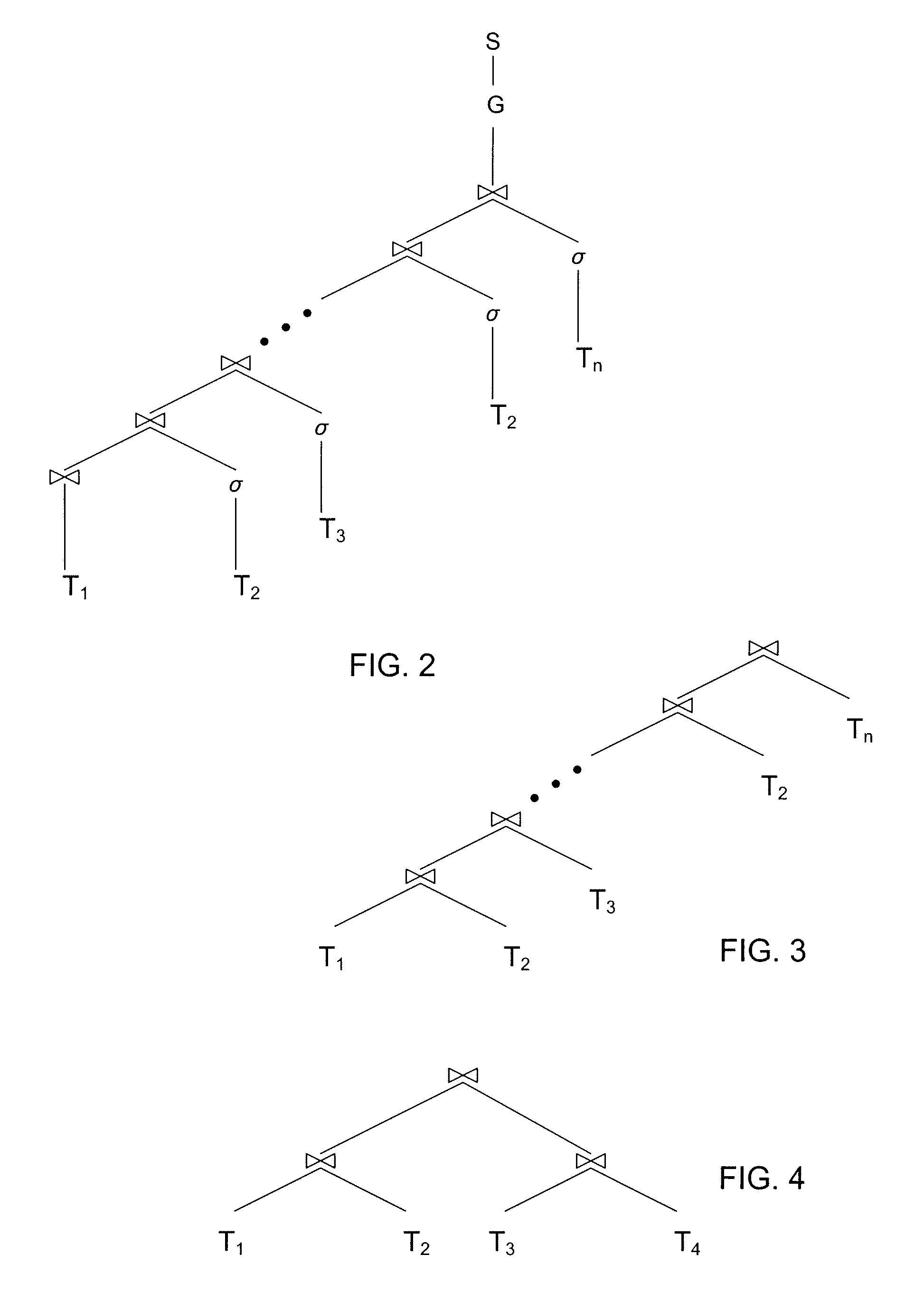
[0065]Particular embodiments of the subject matter described in this specification can be implemented to realize one or more of the following advantages. The scope of queries that can be optimized is expanded beyond queries that only represent snowflake schemas. We have developed a way of generating logical access plans for queries over data warehouses that tends to be scalable and considers a search space that is not in general restricted only to left-deep join trees. The invention finds its principal but not exclusive application in determining access plans for queries that, when applied to the databases that they target, define a plurality of independent snowflake schemas. In accordance with the invention, the plan generator computes, separately for each of the independent snowflake schemas, a constituent logical access plan for obtaining from that schema's tables a record set that includes the data requested by the query from those tables. Additionally, the plan generator determines a plan for obtaining the query's results from the record sets that will be produced by executing the “subplans” thus computed, and this operation may, for example, be the traditional dynamic-programming join-ordering algorithm. So the space of plans that is considered depends on the query graph's topology. But the operation differs from that of, e.g., Vance and Maier in that the set of allowed bushy plans is limited in accordance with the relationships among the fact tables in the query.
[0066]This approach to plan generation can scale to many more tables than the state-of-the-art approach does. In essence, this is because it partitions the set of tables for which a plan must be constructed, and the record sets generated by executing the subplans for the different partitions' queries are treated as the table inputs to the final plan-generation operation. So, if every partition consisted, for example, of five to six tables, this approach could in a reasonable amount of time generate a good plan for queries of seventy-five tables or more.
[0067]In some embodiments, the approach used to determine each of the constituent plans is “greedy” in the sense that the criterion used to select tables to be joined at a given stage in the query's execution is independent of selections made for any subsequent stage. Use of the resultant “lightweight” plan-selection operations contributes to scalability.
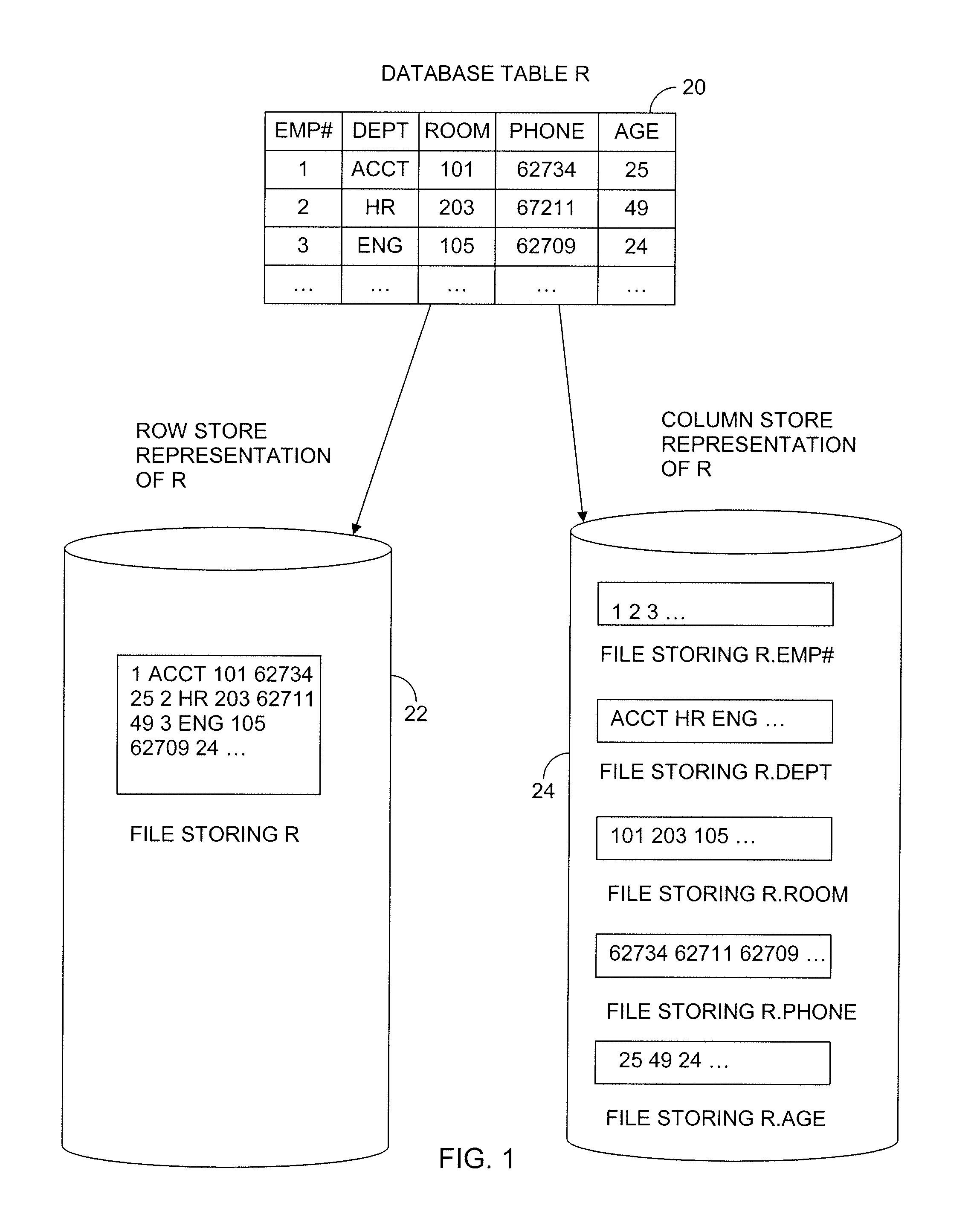
[0069]The invention works particularly well on column-store databases. As will be seen below, it readily lends itself to taking advantage of materialized views that the database may provide, particularly materialized views that are pre-computed joins (as opposed to pre-computed aggregates). A join materialized view has the advantage that it is very general and can be used to process a large number of queries that use that join. With star schemas, a query will contain as many joins as there are required dimensions. This could be a fairly large number. Eliminating them from the query-processing cost is a big advantage. But materializing the join of two or more relations conceptually creates a wide row, and a row store would have to store these wide tuples in each disk block and thereby exacerbate the problem of having to read more data than a given query might need. In contrast, the wide tuple does not present such a problem in a column store.

Problems solved by technology

But the operation differs from that of, e.g., Vance and Maier in that the set of allowed bushy plans is limited in accordance with the relationships among the fact tables in the query.

Method used


Image

  • Query optimizer with schema conversion
  • Query optimizer with schema conversion
  • Query optimizer with schema conversion

Examples


Embodiment Construction

[0098]The present invention's teachings are applicable to a wide range of database systems implemented in essentially any type of computer system. An example is the computer system that FIG. 5 depicts. That drawing's computer system 26 includes a microprocessor 28. Data that the microprocessor 28 uses, as well as instructions that it follows in operating on those data, may reside in on-board cache memory or be received from further cache memory 30, possibly through the mediation of a cache controller 32. That controller can in turn receive such data and instructions from system read / write memory (“RAM”) 34 through a RAM controller 36 or from various peripheral devices through a system bus 38. Alternatively, the instructions may be obtained from read-only memory (“ROM”) 40, as may some permanent data.

[0099]The processor may be dedicated to DBMS operations, or it may additionally execute processes directed to other functions, and the memory space made available to DBMS operations may ...


PUM


Abstract

Methods, program products and systems for determining, for a database query that does not represent a snowflake schema, a graph comprising vertices each representing a table joined in the query, a directed edge between each pair of vertices of which a first vertex represents a first table and a second vertex represents a second table that is joined in the query with the first table, each of the edges representing one of an outer join and an inner join. Further determining, for the graph, a directed spanning tree that represents an ordering of joins in the query and includes all outer join edges in the graph.

Description

CROSS-REFERENCE TO RELATED APPLICATIONS[0001]This application is a continuation-in-part application of, and claims priority to, U.S. patent application Ser. No. 11 / 461,937, entitled Optimizing Snowflake Schema Queries, to inventors Cherniack, et al., which was filed on Aug. 2, 2006. The disclosure of the above application is incorporated herein by reference in its entirety.BACKGROUND OF THE INVENTIONA. Data Warehouses[0002]Conventional database systems were developed in the 1970's to deal with applications in which workloads were dominated by writes. Consider a bank in which a teller initiates high-priority database transactions. Each transaction's goal is to reflect customer withdrawals and deposits quickly and accurately in the database. Applications of this nature are sometimes characterized by the term On-Line Transaction Processing (OLTP). OLTP is concerned more with making writes fast than with expediting reads. These applications typically need access to the most-current data...

Claims


Application Information

Patent Timeline
Patent Type & Authority Patents(United States)
IPC IPC(8): G06F17/30
CPCG06F17/30466G06F16/24544
Inventor LAMB, ANDREWCHERNIACK, MITCHLAWANDE, SHILPATRAN, NGA
Owner MICRO FOCUS LLC
Why Eureka
Eureka Blog
Learn More