
Orthopaedic implant with sensors

a technology of sensors and orthopaedic implants, applied in the field of orthopaedic implants, can solve the problems of increased risk to the health of patients, insufficient x-rays for accurate diagnosis, and unable to fully heal fractures

Active Publication Date: 2011-12-27
SYNTHES USA
View PDF221 Cites 66 Cited by
  • Summary
  • Abstract
  • Description
  • Claims
  • Application Information

AI Technical Summary

Benefits of technology

"The present invention is an orthopaedic implant that has microchips and sensors integrated into it for the purpose of gathering information about the implant and its environment. The implant can be used for fixation of bones and has the ability to receive physical stimulus from the patient's tissue or from the implant itself. The microchip can also store and release therapeutic agents based on the data it receives. The implant can have a coating that acts as a carrier for pharmaceutically active agents or other therapeutic substances. The sensors on the implant can be configured to receive strain, pressure, temperature, and other physical stimuli, and can also emit electric current for bone growth. The implant can also have a counter for counting the number of loading cycles applied to it. The invention also includes a monitoring system that can continuously record the data received from the implant and display it for user review."

Problems solved by technology

In some instances, however, improper installation, implant failure, infection or other conditions such as patient non-compliance with prescribed post-operative treatment may contribute to compromised healing of the fracture, as well as increased risk to the health of the patient.
However, x-rays may be inadequate for accurate diagnoses.
They are costly, and repeated x-rays may be detrimental to the patient's and health care workers' health.
In some cases, non-unions of fractures may go clinically undetected until implant failure.
Moreover, x-rays may not be used to adequately diagnose soft tissue conditions or stress on the implant.

Method used


Image

  • Orthopaedic implant with sensors
  • Orthopaedic implant with sensors
  • Orthopaedic implant with sensors

Examples


Embodiment Construction

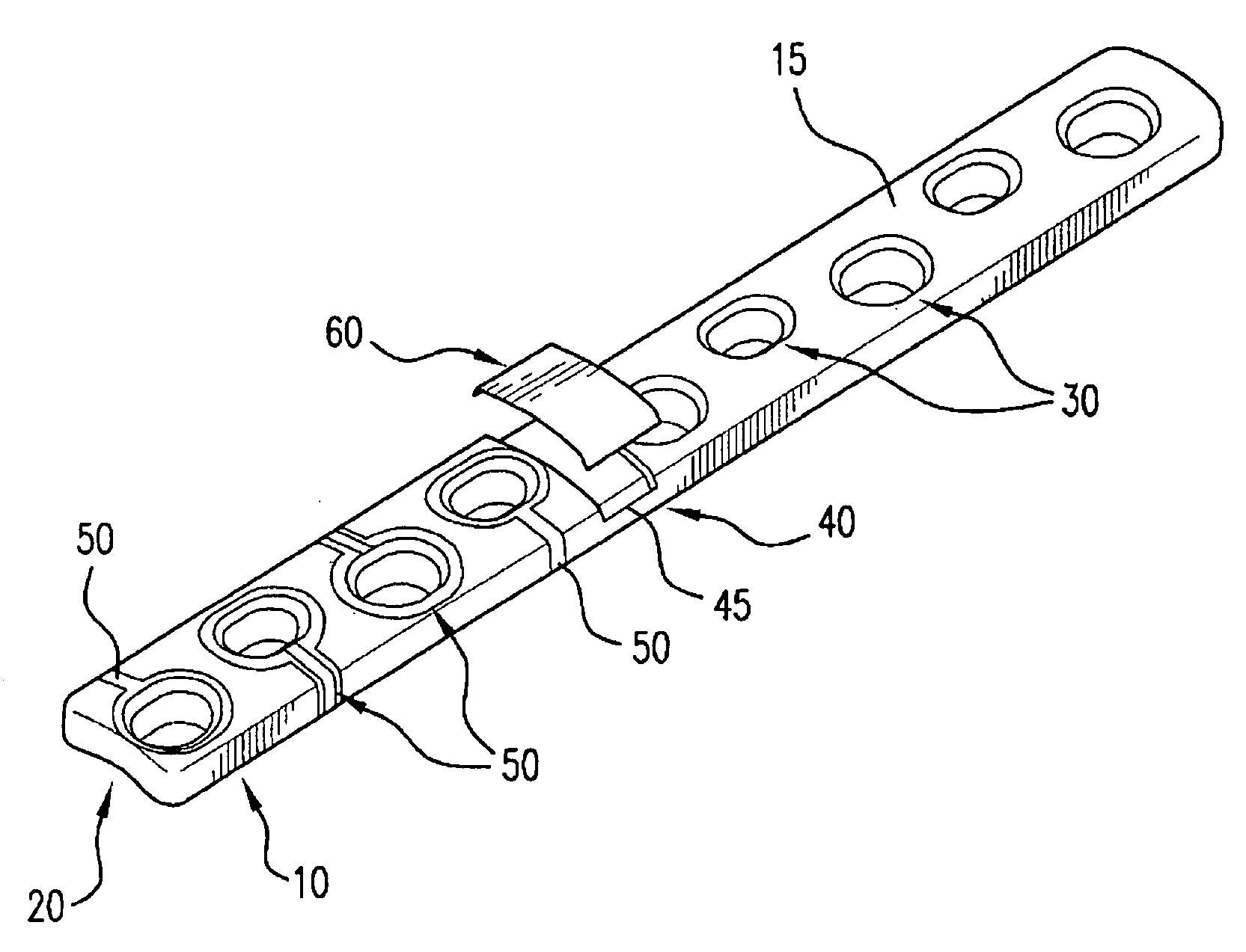
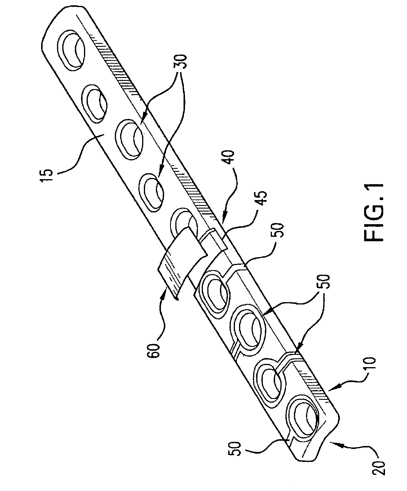
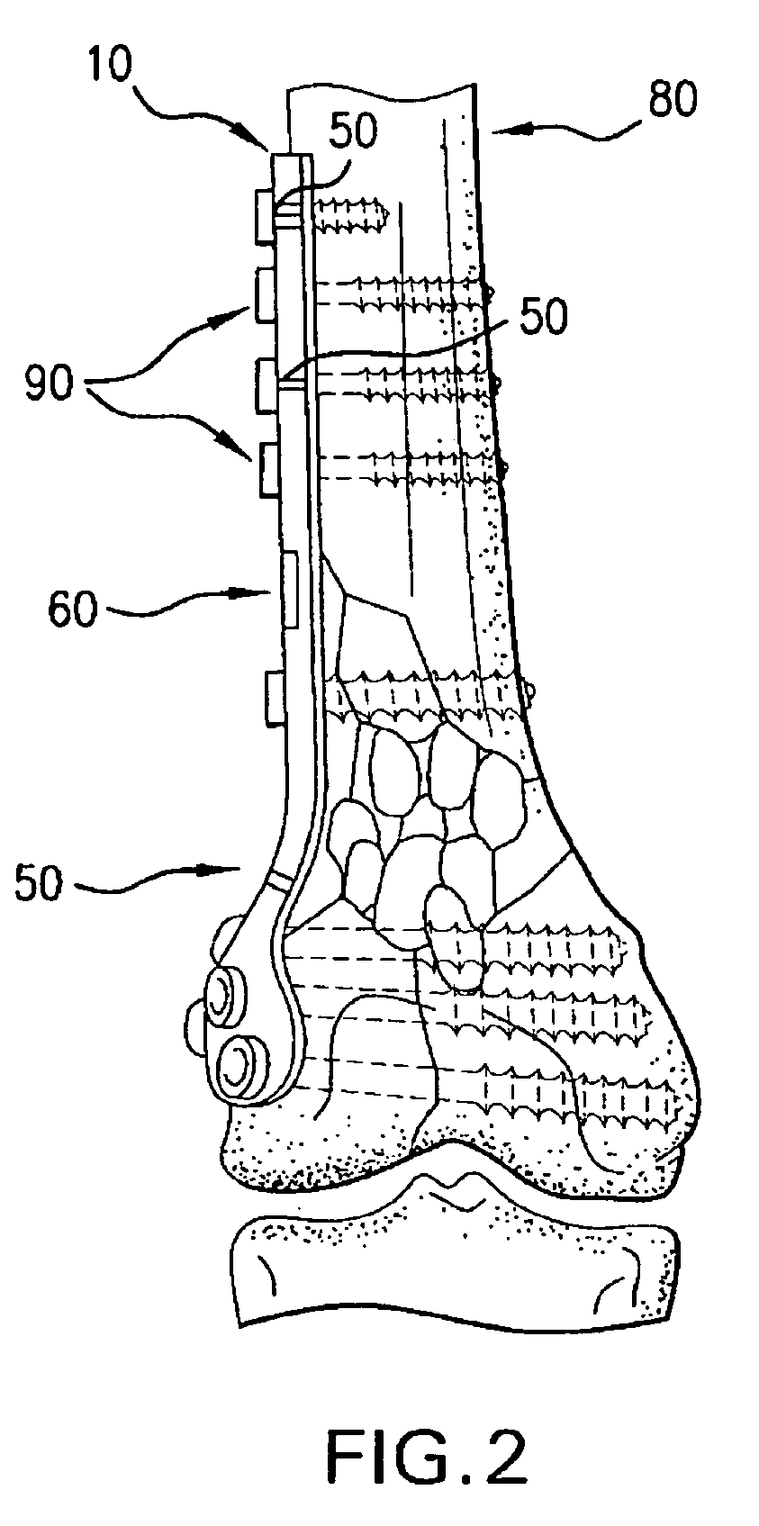
Reference is now made to FIGS. 1-2, which show a bone plate 10 according to a first preferred embodiment of the present invention. The bone plate 10 shown in FIG. 1 comprises upper surface 15 and lower surface 20, with the lower surface 20 configured to contact the bone. The plate may further have a number of holes 30 configured and adapted to receive fasteners, such as, for example, screws, that will affix the bone plate to the bone. One or more microchips 40 may be located on the plate top surface 15, bottom surface 20, the side wall of the bone plate, or as with the illustrated embodiment, may be placed within a compartment 45 in the bone plate for recording information gathered by numerous sensors 50 which may be located at various locations anywhere on the top, bottom or sides of the plate, or may surround or be located within the plate holes. The sensors may be located on the surface of the plate, or they may be embedded therein. A small cover 60 may be provided to conceal and...


PUM

PropertyMeasurementUnit
perimeteraaaaaaaaaa
poweraaaaaaaaaa
pressureaaaaaaaaaa

Abstract

The present invention relates to an orthopaedic implant, such as a bone plate, for the fixation of bone where the implant also has at least one microchip and at least one sensor connected to the microchip. The sensor or sensors are configured to receive physical stimulus from a portion of the implant or the patient's tissue such as temperature, pressure, and strain. The information received from the sensor or sensors is gathered by the microchip and transmitted to a receiver, such as a personal computer, outside the patient. This information enables doctors to diagnose the useful life of the implant, the load sharing of the bone plate, and possible complications typically associated with orthopaedic implants such as infection, fracture non-union, and fatigue. The implant may also have one or more electrodes located on its surface which emit an electric current to stimulate healing of the broken or fractured bone.

Description

FIELD OF THE INVENTIONThe present invention relates to orthopaedic implants, such as bone plates, for use in repairing fractured bones or for addressing other orthopedic conditions. More particularly, the present invention relates to an orthopaedic implant having sensors and / or a microchip for measuring and transmitting data concerning the implant and / or the surrounding tissue to doctors and / or patients.BACKGROUND OF THE INVENTIONBone plates have been used for many years in the field of orthopedics for the repair of broken bones and are well known in the art. One example of such a bone plate is shown and described in U.S. Pat. No. 6,623,486 to Weaver, et al. which is hereby incorporated by reference. Such bone plates function well in most instances, and fracture healing occurs more predictably than if no plate were used. In some instances, however, improper installation, implant failure, infection or other conditions such as patient non-compliance with prescribed post-operative trea...

Claims


Application Information

Patent Timeline
Patent Type & Authority Patents(United States)
IPC IPC(8): A61B17/58A61B5/00A61B5/07A61B5/103A61B17/00A61B17/60A61B17/64A61B17/66A61B17/70A61B17/72A61B17/80A61B17/86A61B19/00A61F2/00A61F2/02A61F2/28A61F2/30A61F2/44A61F2/46A61N1/20
CPCA61B5/076A61B5/14539A61B5/411A61B5/4504A61B5/4839A61B17/80A61B19/46A61N1/205A61B5/01A61B17/60A61B17/64A61B17/663A61B17/70A61B17/7001A61B17/7037A61B17/72A61B17/7225A61B17/86A61B2017/00084A61B2017/00734A61B2019/464A61B2560/0219A61F2/442A61F2002/2821A61F2002/3067A61F2002/30677A61F2002/4666A61F2002/4672A61F2250/0002A61F2310/0097A61B2090/064A61B90/06A61B17/58A61B17/68
Inventor MORGAN, CHADHALL, IV, HARRY T.GREEN, JAMES M.FLEXNER, GEOFFREYGELTZ, CHARLES E.
Owner SYNTHES USA
Learn More