
System for enhancing sonotrode performance in ultrasonic additive manufacturing applications

a technology of additive manufacturing and ultrasonic welding, applied in the direction of mechanical vibration separation, manufacturing tools, instruments, etc., can solve the problems of loss of displacement of target media, local melting of plastic, and insufficient melting of base materials

Active Publication Date: 2011-12-27
FABRISONIC
View PDF9 Cites 22 Cited by
  • Summary
  • Abstract
  • Description
  • Claims
  • Application Information

AI Technical Summary

Benefits of technology

"The present invention provides an ultrasonic welding assembly and device for use in ultrasonic additive manufacturing. The assembly includes a sonotrode with a single welding region and two nodal regions, a mounting plate for supporting the sonotrode, ultrasonic transducers, a diaphragm spring, roller bearings, linear guides, low-friction linear bearings, and brush mount units. The device also includes a force application region on the mounting plate for applying force to the welding region of the sonotrode. The technical effects of the invention include improved welding efficiency, flexibility, and stability of the ultrasonic welding process."

Problems solved by technology

Ultrasonic welding of thermoplastics results in local melting of the plastic due to absorption of vibration energy.
Although there is heating, it is not enough to melt the base materials.
Current UAM technology utilizes titanium based tools which tend to wear rapidly, often resulting in a loss of displacement of the target media due to insufficient interaction of worn texture profiles during the ultrasonic welding process.

Method used


Image

  • System for enhancing sonotrode performance in ultrasonic additive manufacturing applications
  • System for enhancing sonotrode performance in ultrasonic additive manufacturing applications
  • System for enhancing sonotrode performance in ultrasonic additive manufacturing applications

Examples


Embodiment Construction

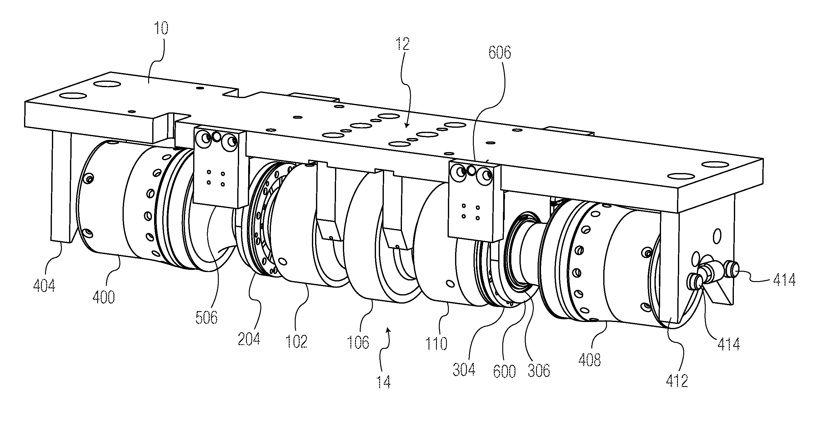
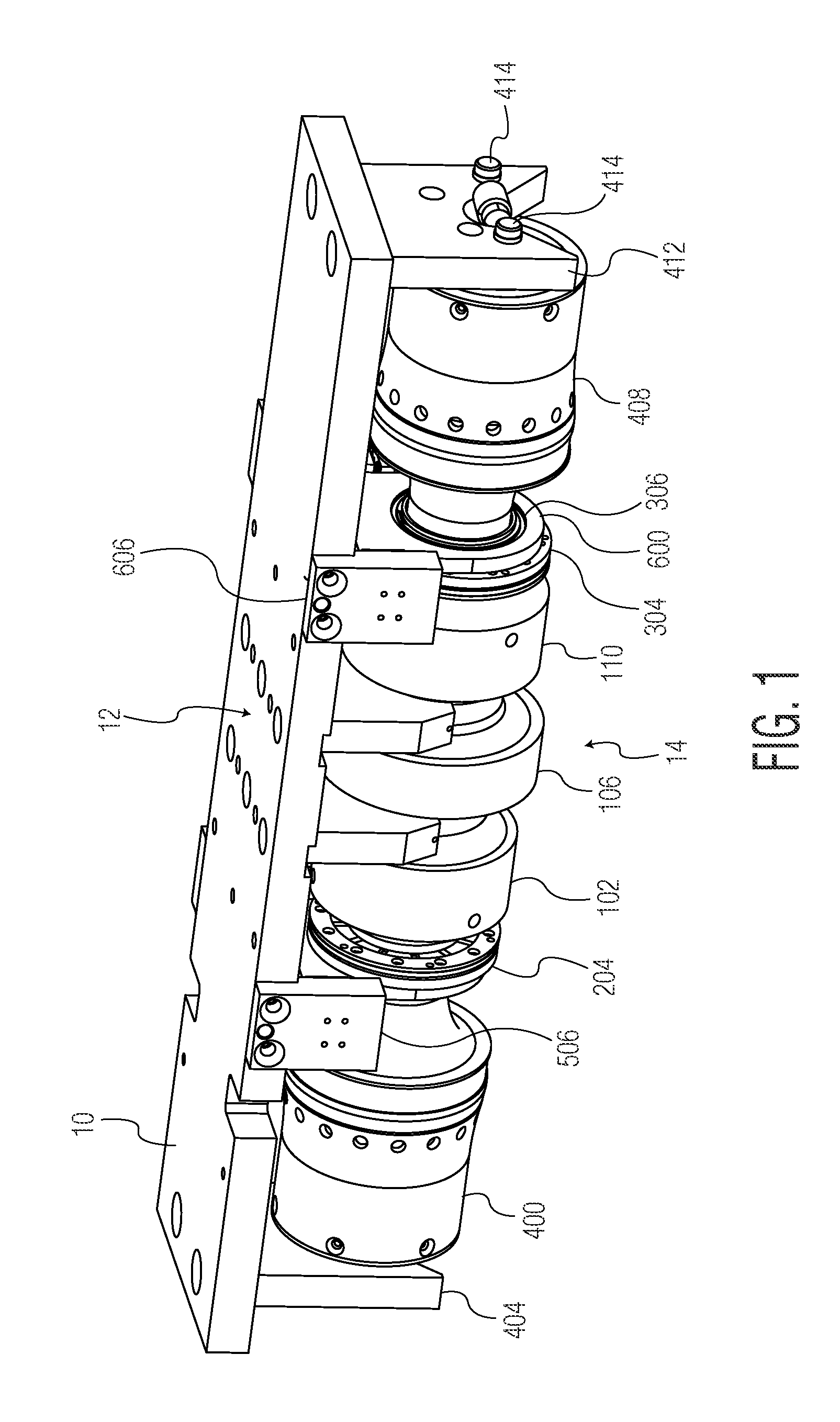
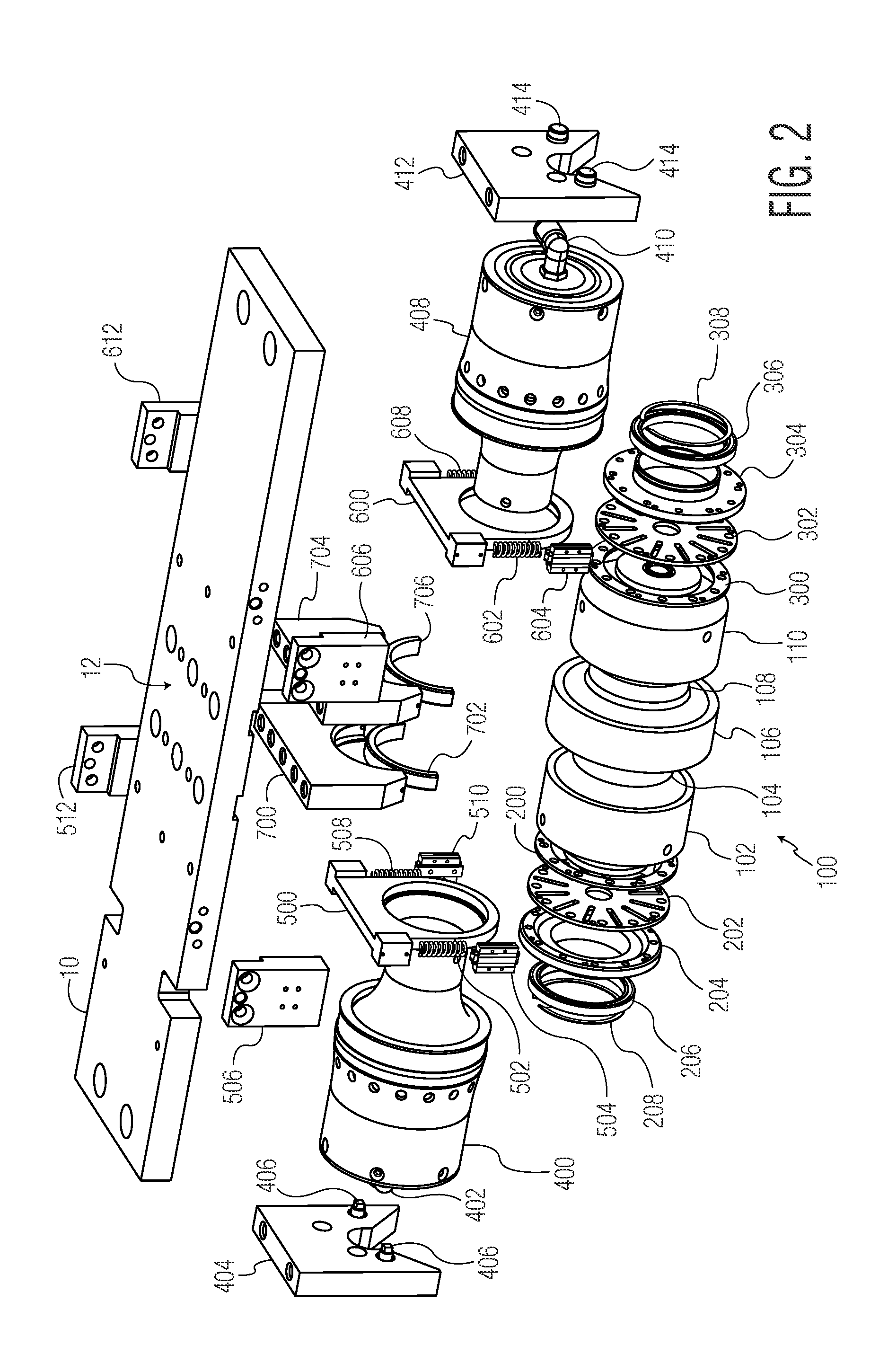
[0018]Exemplary embodiments of the present invention are now described with reference to the Figures. Reference numerals are used throughout the detailed description to refer to the various elements and structures. Although the following detailed description contains many specifics for the purposes of illustration, a person of ordinary skill in the art will appreciate that many variations and alterations to the following details are within the scope of the invention. Accordingly, the following embodiments of the invention are set forth without any loss of generality to, and without imposing limitations upon, the claimed invention.

[0019]The present invention relates to an advanced tool design that increases or enhances the performance of sonotrodes used in ultrasonic additive manufacturing (UAM) processes for metals, plastics, and textiles. More specifically, this invention provides more efficient energy transmission to the materials interface creating a superior weld and greatly inc...


PUM

PropertyMeasurementUnit
frequencyaaaaaaaaaa
frequencyaaaaaaaaaa
frequencyaaaaaaaaaa

Abstract

An ultrasonic welding assembly, comprising: a sonotrode having a single welding region and two nodal regions formed on either side of the welding region; a mounting plate for supporting the sonotrode having a force application region on the upper surface thereof; at least one ultrasonic transducer connected to the sonotrode; at least one diaphragm spring disposed between the ultrasonic transducer and the sonotrode; at least one roller bearing connected to the diaphragm spring; at least two linear guides connected to the roller bearing, wherein the at least two linear guides are connected to the mounting plate and support the roller bearing and the sonotrode in a flexible manner; and first and second low-friction linear bearings in contact with nodal regions for the application of downward force to the sonotrode, wherein the first and second linear bearings are connected to the mounting plate.

Description

STATEMENT REGARDING FEDERALLY SPONSORED RESEARCH[0001]This invention was made with support under Contract No. DAAD19-03-2-0002 awarded by the U.S. Army. The U.S. Government has certain rights in the invention.BACKGROUND OF THE INVENTION[0002]The described invention relates in general to ultrasonic welding systems and more specifically to a device and method for enhancing the performance of sonotrodes used in ultrasonic additive manufacturing applications.[0003]Ultrasonic welding is an industrial process involving high-frequency ultrasonic acoustic vibrations that are locally applied to workpieces being held together under pressure to create a solid-state weld. This process has applications in the electrical / electronic, automotive, aerospace, appliance, and medical industries and is commonly used for plastics and especially for joining dissimilar materials. Ultrasonic welding of thermoplastics results in local melting of the plastic due to absorption of vibration energy. The vibratio...

Claims


Application Information

Patent Timeline
Patent Type & Authority Patents(United States)
IPC IPC(8): B32B37/00
CPCB23K20/103B23K20/106G10K11/004F16C23/08B06B3/00B29C66/816B29C66/8161B29C66/83411B29C65/085B29C66/8167B29C66/8145B33Y30/00B32B37/00
Inventor SHORT, MATTHEW A.
Owner FABRISONIC
Learn More