
Photosensor for display device

a technology of display device and photosensor, which is applied in the field of photosensors, can solve the problems of voltage damage to the sensor transistor, and achieve the effects of wide sensing range, less constituting components, and improved operation li

Active Publication Date: 2011-12-20
WINTEK CORP
View PDF5 Cites 2 Cited by
  • Summary
  • Abstract
  • Description
  • Claims
  • Application Information

AI Technical Summary

Benefits of technology

[0009]The invention relates to a photosensor for a display device having comparatively less constituting components, a wide sensing range, and an improved operation life.
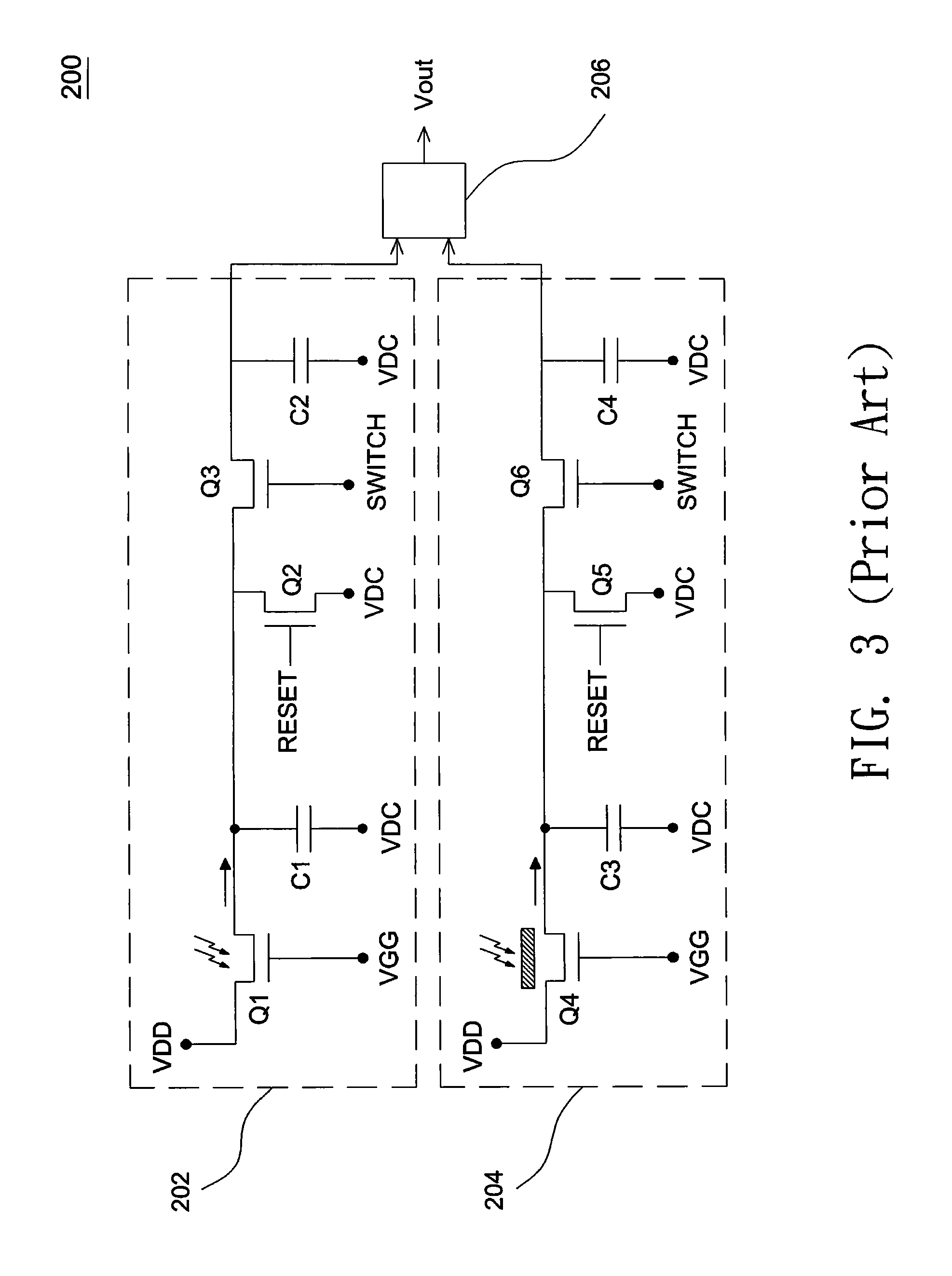
[0012]According to the above embodiments, during each reset operation of the photosensor, the voltage level in a storage capacitor is reduced to the threshold voltage of the third transistor by the auto-zero discharge operation of the reset circuit and then gradually increased by the reception of ambient light. Thereby, a considerable difference between the output photovoltage and the reference voltage is obtained. Further, since the output photovoltage and the reference voltage are both fetched from a same circuit, the constituting components and layout areas are decreased to reduce fabrication costs. Further, the sensor transistor typically operates within a negative bias portion of a transistor operation graph, since the current characteristics are better as the sensor transistor operates within this portion. However, in case the sensor transistor is negatively biased for a long time, it is liable to cause a shift in its threshold voltage to damage the sensor transistor. In comparison, according to the above embodiment, since the gate bias signal triggers one time per frame, the sensor transistor is alternately subjected to a positive bias (positive voltage VGH) and a negative bias (photovoltage) to effectively avoid the threshold voltage shift.

Problems solved by technology

However, in case the sensor transistor is negatively biased for a long time, it is liable to cause a shift in its threshold voltage to damage the sensor transistor.

Method used


Image

  • Photosensor for display device
  • Photosensor for display device
  • Photosensor for display device

Examples


Embodiment Construction

[0024]In the following detailed description of the preferred embodiments, reference is made to the accompanying drawings which form a part hereof, and in which are shown by way of illustration specific embodiments in which the invention may be practiced. In this regard, directional terminology, such as “top,”“bottom,”“front,”“back,” etc., is used with reference to the orientation of the Figure(s) being described. The components of the present invention can be positioned in a number of different orientations. As such, the directional terminology is used for purposes of illustration and is in no way limiting. On the other hand, the drawings are only schematic and the sizes of components may be exaggerated for clarity. It is to be understood that other embodiments may be utilized and structural changes may be made without departing from the scope of the present invention. Also, it is to be understood that the phraseology and terminology used herein are for the purpose of description an...


PUM


Abstract

A photosensor for a display device includes a light receiver, a reset unit, and a sample unit. The light receiver is used for receiving ambient light to generate a photovoltage. The light receiver includes a first transistor and a first conversion unit that transforms the output of the first transistor into the photovoltage. The reset unit is used for providing an initiated reference voltage in response to a reset signal and includes a second transistor and a third transistor that are connected with each other, where the first conversion unit is discharged through the third transistor to obtain the initiated reference voltage when the second transistor is turned on. The sample unit is used for outputting the photovoltage in respond to a sample signal, the sample unit comprising a fourth transistor in respond to the sample signal and a second conversion unit that transforms the output of the fourth transistor into the photovoltage.

Description

CROSS REFERENCE TO RELATED APPLICATION[0001]This application claims priority of application No. 097105669 filed in Taiwan R.O.C on Feb. 19, 2008 under 35 U.S.C. §119; the entire contents of which are hereby incorporated by reference.BACKGROUND OF THE INVENTION[0002]1. Field of the Invention[0003]The invention relates to a photosensor, particularly to a photosensor that is provided in a display device to measure the intensity of ambient light.[0004]2. Description of the Related Art[0005]It has been suggested that an ambient light sensor is provided in a display device to measure the intensity of ambient light and correspondingly adjust the light intensity of a light source built in the display device. Thereby, optimum display contrast can be achieved and power consumption is allowed to be reduced.[0006]FIG. 1 shows an equivalent circuit diagram of a conventional photosensor, and FIG. 2 shows an exemplary timing chart of input signals for the photosensor 100 shown in FIG. 1. Referring...

Claims


Application Information

Patent Timeline
Patent Type & Authority Patents(United States)
IPC IPC(8): G09G5/00
CPCG09G3/20G09G2360/144
Inventor HAN, HSI-RONGCHAN, CHIEN-TING
Owner WINTEK CORP
Learn More