Electrical current sensing apparatus

a technology of electric current and sensing apparatus, which is applied in the direction of air breakers, high-tension/heavy-dress switches, instruments, etc., can solve the problems of large physical limitation, undesirable increase in the overall package size of the electrical switching apparatus, and the need for bulky mounting brackets for transformers, toriod or rogowski coil sensors. , to achieve the effect of wide sensing range, enhanced resolution, and improved immunity to external magnetic fields

Inactive Publication Date: 2017-08-29
EATON INTELLIGENT POWER LTD
View PDF14 Cites 0 Cited by
  • Summary
  • Abstract
  • Description
  • Claims
  • Application Information

AI Technical Summary

Benefits of technology

[0008]Embodiments of the present invention provide a current sensor assembly with a wide sensing range, enhanced resolution, and improved immunity to external magnetic fields.

Problems solved by technology

Each of the aforementioned current sensors includes a physical limitation that is a major disadvantage in constructing a compact electrical switching apparatus.
Transformer, toriod, or Rogowski coil sensors often require bulky mounting brackets.
The second coil or ferrite core of magnetic field sensors must be positioned about the periphery of the conductor of interest and results in an undesirable increase in the overall package size of the electrical switching apparatus.
Further, in multi-phase devices such as a three phase motor starter that includes separate, closely spaced conductors, the potential for cross-talk, or interference between the current sensors becomes quite high.
In addition to being susceptible to external magnetic fields, present magnetic field current sensors are also limited in their sensing range and resolution.

Method used


Image

  • Electrical current sensing apparatus
  • Electrical current sensing apparatus
  • Electrical current sensing apparatus

Examples


Embodiment Construction

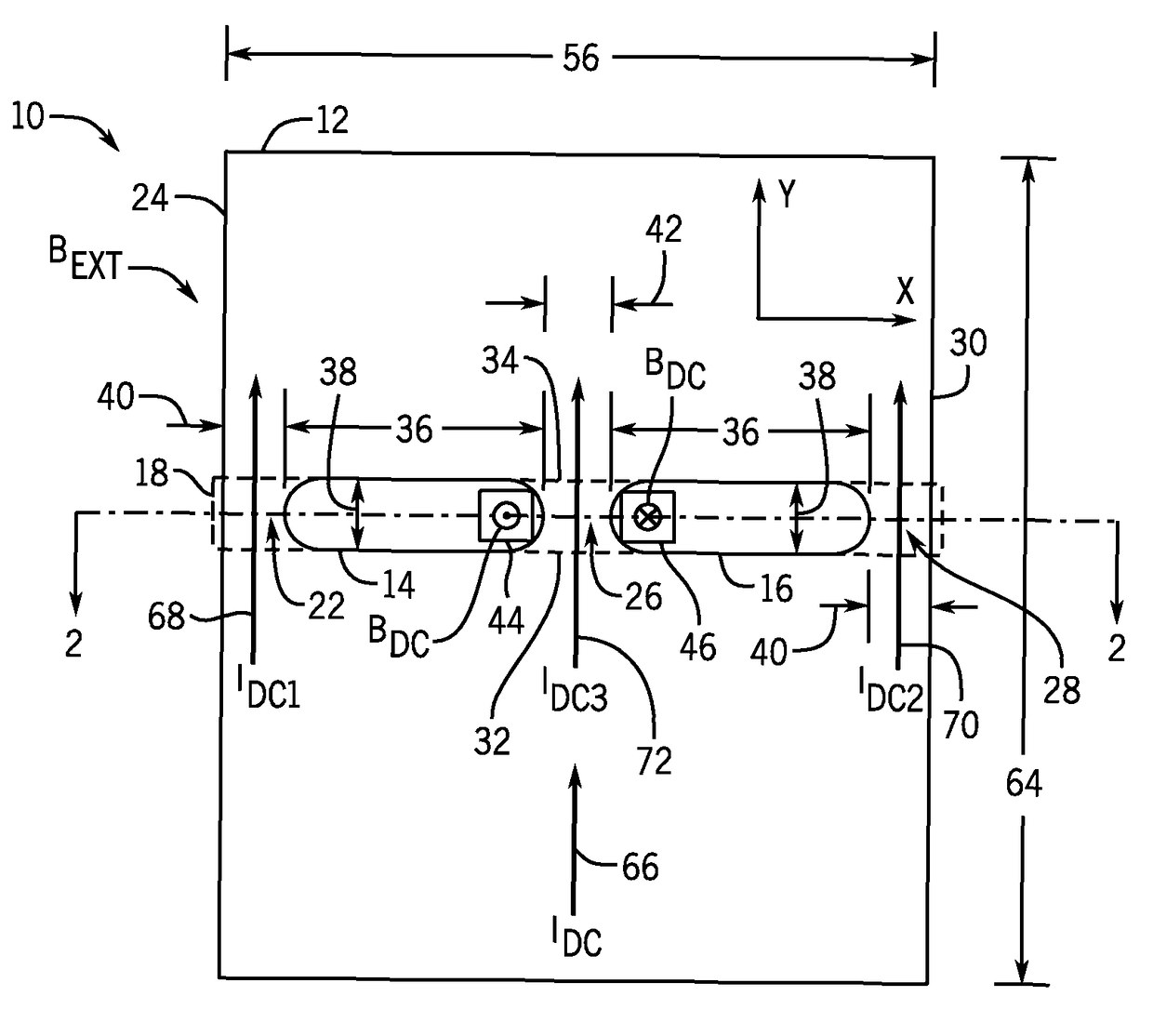
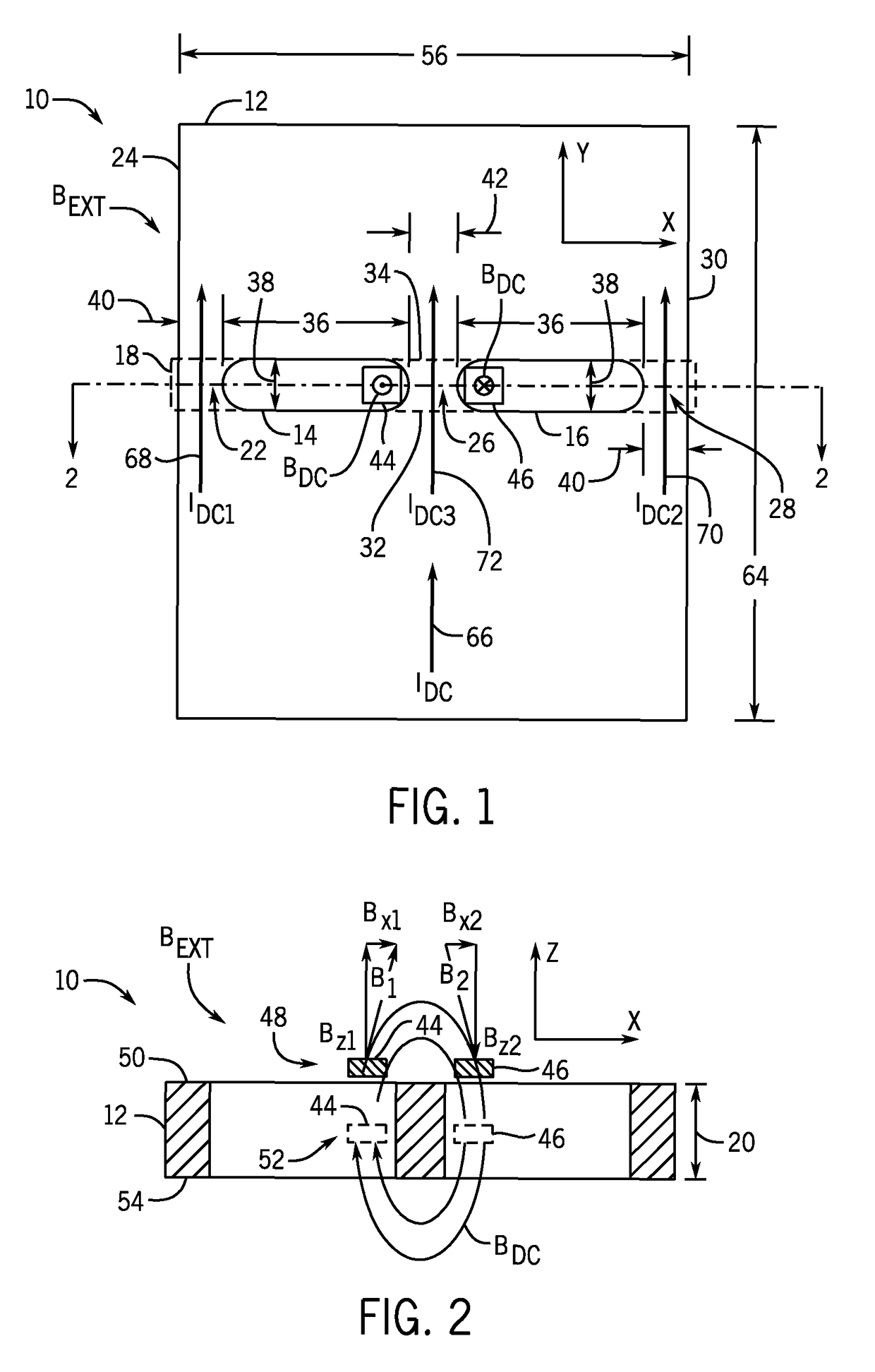
[0025]The embodiments of the invention set forth herein relate to an apparatus that senses an electrical current in a conductor. Referring first to FIGS. 1 and 2, a current sensing assembly 10 includes a conductor 12 or bus bar having a first slot 14 and a second slot 16 formed in a current sensing region 18 of the conductor 12. In one embodiment, conductor 12 is constructed of a magnetic material such as ferrous iron or steel, as non-limiting examples. As shown in FIG. 2, slots 14, 16 extend through a thickness 20 of conductor 12. First and second slots 14, 16 are sized and positioned on conductor 12 to form a first current path region 22 located adjacent a left edge 24 of conductor 12, a central current path region 26, and a second current path region 28 located adjacent the right edge 30 of conductor 12. As shown, the first current path region 22 is positioned between the left edge 24 of conductor 12 and first slot 14 while the second current path region 28 is positioned between ...


PUM


Abstract

A current sensing apparatus is disclosed that provides improved immunity to external magnetic fields, enhanced resolution, and a wide sensing range. The current sensing apparatus includes a conductor having a plurality of current path regions formed therein, which are separated by a pair of slots formed through the conductor. A pair of magnetic field sensors is positioned relative to the pair of slots to sense a magnetic field produced by a current flow through one of the current path regions.

Description

CROSS-REFERENCE TO RELATED APPLICATION[0001]The present application is a continuation in part of, and claims priority to, U.S. non-provisional application Ser. No. 14 / 102,660, filed Dec. 11, 2013, and a continuation in part of, and claims priority to, U.S. non-provisional application Ser. No. 14 / 102,675, filed Dec. 11, 2013, the disclosures of which are incorporated herein by reference in their entireties.BACKGROUND OF THE INVENTION[0002]Embodiments of the invention relate generally to current sensors and, more particularly, to an apparatus for sensing electrical current flowing through a conductor.[0003]Electrical switching apparatus, such as circuit interrupters, relays, and motor soft starters, often include one or more current sensor configured to measure the current flowing through the electrical switching apparatus. Known current sensors include a current transformer with a matching current meter, a ferrite toroid with matching current meter or printed circuit board assembly, ...

Claims


Application Information

Patent Timeline
Patent Type & Authority Patents(United States)
IPC IPC(8): G01R15/20H01H33/02
CPCG01R15/207H01H33/027
Inventor JUDS, MARK ALLANLUDWIG, DALE RICHARD
Owner EATON INTELLIGENT POWER LTD
Why Eureka
Try Eureka