
Method for positron emission tomography and PET scanner

a tomography and positron emission technology, applied in tomography, instruments, dosimeters, etc., can solve the problem that the detection probability of each signal line in a bundle is not necessarily uniform, and achieve the effect of improving the signal-to-noise ratio and improving image quality

Active Publication Date: 2011-12-20
FORSCHUNGSZENTRUM JULICH GMBH
View PDF4 Cites 1 Cited by
  • Summary
  • Abstract
  • Description
  • Claims
  • Application Information

AI Technical Summary

Benefits of technology

This approach results in more accurate tomographic reconstructions with improved signal-to-noise ratio and better image quality by accurately representing the true information content of detected coincidences, reducing noise and artifacts.

Problems solved by technology

Furthermore, the detection probability of each signal line of a bundle is not necessarily uniform due to geometric effects.

Method used


Image

  • Method for positron emission tomography and PET scanner
  • Method for positron emission tomography and PET scanner
  • Method for positron emission tomography and PET scanner

Examples


embodiment 1

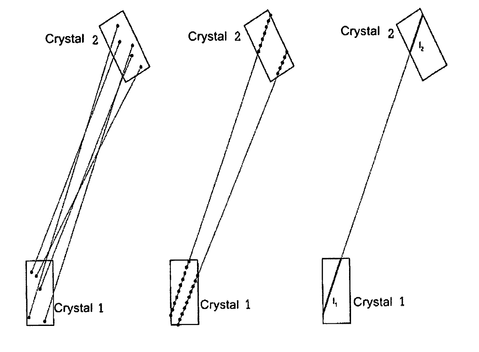
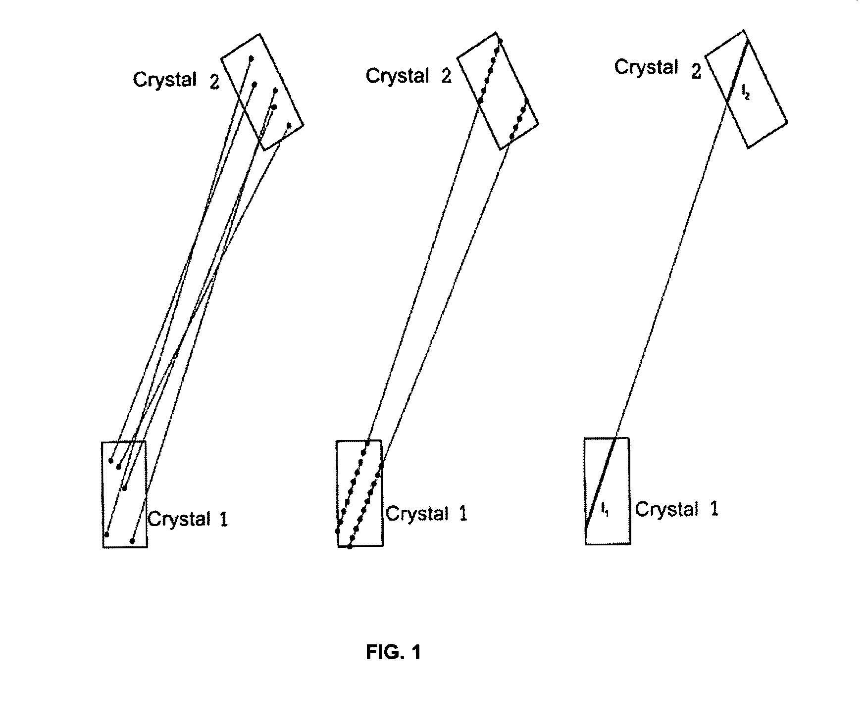
[0023] (left) individual, randomly determined points in both crystals in each case define an observed signal line, (center) different combinations of certain points form the same signal line.

embodiment 2

[0024] (right) the effective weighting of a signal line (LOR) results from the product of p12=I1*I2 of the intersecting lengths of this LOR with the crystals involved.

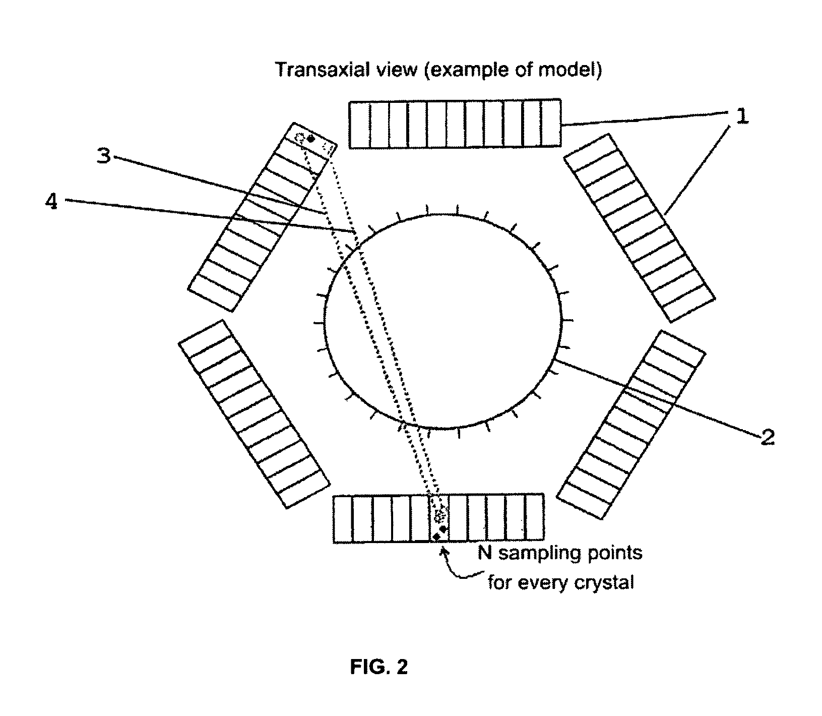
[0025]FIG. 2 shows a transaxial view of an irregular detector topology 1 (outer part) and a virtual regular cylinder detector 2 (VRZ, inner part). The VRZ is used in the embodiment of the method according to the invention in which the points of intersection of each signal line to be considered for this reconstruction are determined by way of the VRZ and are treated in the reconstruction as if detectors had been present there. Each physical signal line 3, 4 (LOR) intersects the cylinder in exactly two unequivocal points. For the association of the points of intersection, the cylinder is segmented into a finite number of partial surfaces (virtual detectors) by introducing cylinder rings and regular ring subsets. Each point of intersection of the LOR with the cylinder is located on a unequivocally determined partial surfa...


PUM


Abstract

Disclosed is a method for positron emission tomography and to a PET scanner. The positron emission tomography method employs the following steps: a) two photons are emitted in opposite directions by an annihilation event in the sample, b) at least two of a plurality of detectors arranged around the sample are prompted to output a signal by the two photons, c) a signal line on which the event may have taken place is determined from the location of the detectors which have output a signal, d) this signal line is evaluated in the tomographic reconstruction of the sample, wherein for each event a plurality of signal lines are determined and evaluated in the tomographic reconstruction of the sample. As described at the outset, the reconstructed image thus becomes more accurate and noise is reduced. The method and the apparatus can improve the signal-to-noise ratio of images.

Description

[0001]The invention relates to a method for positron emission tomography and to a PET scanner.[0002]Positron emission tomography (PET) employs scintillation detectors, which detect the photons emitted in pairs in opposite directions during the annihilation of electron-positron pairs in the sample.BACKGROUND OF THE INVENTION[0003]In a PET measurement, the key is to detect the annihilation of electron-positron pairs in the sample and to localize the signal line on which the respective event has taken place. Based on a plurality of such events, it is then possible to determine the inner activity distribution of the sample using tomographic reconstruction.[0004]During each event, two photons are emitted simultaneously in opposite directions, the spatial orientation thereof not being predictable, as this is isotropic. For this reason, a plurality of detectors are arranged around the sample in a PET scanner, thereby ensuring that each of the two photons resulting from an event strikes a d...

Claims


Application Information

Patent Timeline
Patent Type & Authority Patents(United States)
IPC IPC(8): G01T1/10
CPCG01T1/1648G01T1/2985A61B6/037
Inventor SCHEINS, JUERGEN JOHANN
Owner FORSCHUNGSZENTRUM JULICH GMBH
Learn More