
Accelerometers

Active Publication Date: 2011-12-20
OPTASENSE HLDG LTD
View PDF39 Cites 19 Cited by
  • Summary
  • Abstract
  • Description
  • Claims
  • Application Information

AI Technical Summary

Benefits of technology

[0008]It will be recognised that a suitable compliant material for the cylinder will have a relatively low Young's modulus but with a Poisson's ratio close to 0.5, such that the stiffness of the accelerometer arises more from the circumferential winding than the cylinder itself. Thus for a particular force acting on the cylinder, the greater the strain induced in the fibre and hence sensitivity of the accelerometer. Furthermore, by constraining the seismic mass coaxially within the cylinder, the tendency present in prior art devices for the cylinder to buckle or otherwise respond unfavourably to acceleration orthogonal to the cylinder axis is limited. Advantageously, this leads to improved performance of devices incorporating the accelerometer in which sensitivity in a single axis is paramount.
[0009]It will be further recognised that by reducing the wall thickness of the cylinder the sensitivity of the accelerometer can be still further increased. Prior art devices have hitherto sought to increase sensitivity either by increasing the seismic mass and / or the height of the cylinder supporting the seismic mass. Both approaches whilst increasing the desired sensitivity may also have the problem of increased sensitivity to orthogonal acceleration mentioned above and will result in an increased accelerometer size. With the trend towards miniaturisation of components, the present invention lends itself to providing improved performance to prior art devices for a given volume and mass.

Problems solved by technology

Furthermore, by constraining the seismic mass coaxially within the cylinder, the tendency present in prior art devices for the cylinder to buckle or otherwise respond unfavourably to acceleration orthogonal to the cylinder axis is limited.
Both approaches whilst increasing the desired sensitivity may also have the problem of increased sensitivity to orthogonal acceleration mentioned above and will result in an increased accelerometer size.

Method used


Image

  • Accelerometers
  • Accelerometers
  • Accelerometers

Examples


Embodiment Construction

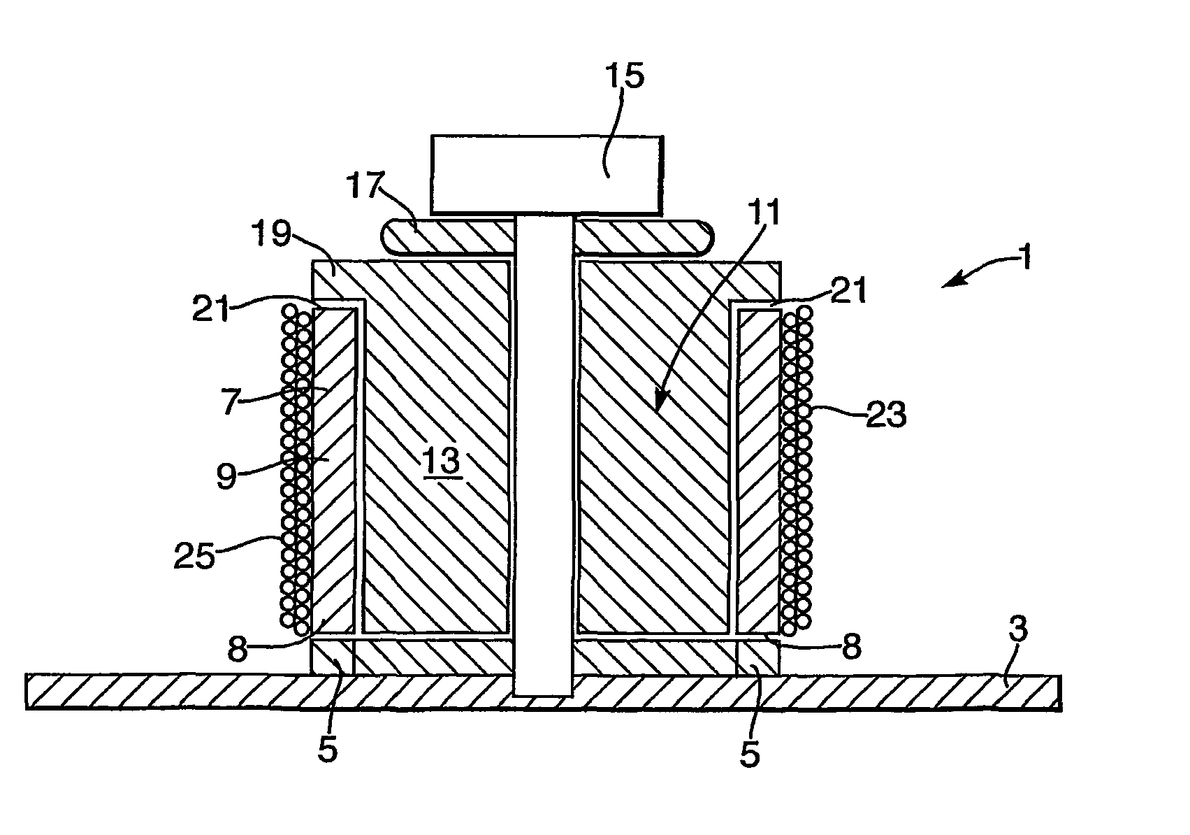
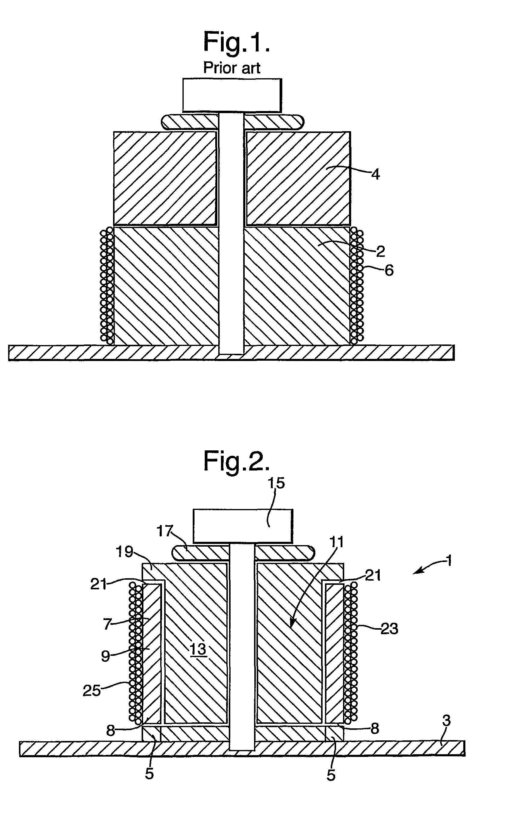
[0019]Referring now to FIG. 2, the fibre optic accelerometer 1 is mounted on a base plate 3 via a rigid support ring 5. The ring 5 can be formed either as a relief in the base plate 3 or perhaps more conveniently, it can be provided as a separate component, thereby allowing differing sizes of accelerometer 1 to be mounted on the base plate 3. The base plate 3 itself is produced from a rigid material, typically steel although other metals and composites may suggest themselves to those skilled in the art. Furthermore, it should be understood that references throughout the description to a base plate are also intended to encompass the direct mounting of the accelerometer to a platform or other structure.

[0020]The support ring 5 is in contact with a first end face of a compliant cylindrical member 7. The cylindrical member has relatively thin wall 9 and a coaxial void 11 such that a seismic mass 13 may be received therein. The compliant cylindrical member 7 is formed from a material hav...


PUM


Abstract

A fibre optic accelerometer particularly intended for use with an interferometer using the compliant cylinder approach but further providing a seismic mass at the core of the cylinder resulting in improved sensitivity and rejection of out-of-axis inputs.

Description

BACKGROUND OF THE INVENTION[0001](1) Field of the Invention[0002]The present invention relates to accelerometers and particularly fibre optic accelerometers for use in interferometers.[0003](2) Description of the Art[0004]The need to monitor extremely low levels of vibration in areas such as security, seismic survey and condition monitoring of machinery and such like has spurred the development of ever more sensitive accelerometers. Fibre optic technology has been applied to this particular field in the form of fibre-optic accelerometers based on interferometric techniques. The compliant cylinder approach to the design of a fibre-optic accelerometer is particularly effective when incorporated in such an interferometer. In one known approach a seismic mass is held in place by two compliant cylinders and around the circumference of each cylinder there being wound a single mode optical fibre, which form the arms of an interferometer. In another approach, a single compliant cylinder 2 l...

Claims


Application Information

Patent Timeline
IPC IPC(8): G01P15/13G01H9/00G01P15/093G01V1/18G02F1/01
CPCG01H9/004G01P15/093G01V1/181G02F1/0134
Inventor CRICKMORE, ROGER IANHILL, JOHN DAVIDWOOLER, JOHN PETER FAIRFAXTHOMAS, PETER JAMES
Owner OPTASENSE HLDG LTD
Learn More