
Design support method, design support system, and design support program for heat convection field

a technology of design support and heat convection, applied in the direction of instruments, cad techniques, analogue processes for specific applications, etc., can solve the problems of difficult to realize optimization within a reasonable amount of time, inapplicability of the boundary condition technique, etc., and achieve the effect of reducing the number of numerical simulations

Active Publication Date: 2011-12-06
OSAKA UNIV +1
View PDF3 Cites 2 Cited by
  • Summary
  • Abstract
  • Description
  • Claims
  • Application Information

AI Technical Summary

Benefits of technology

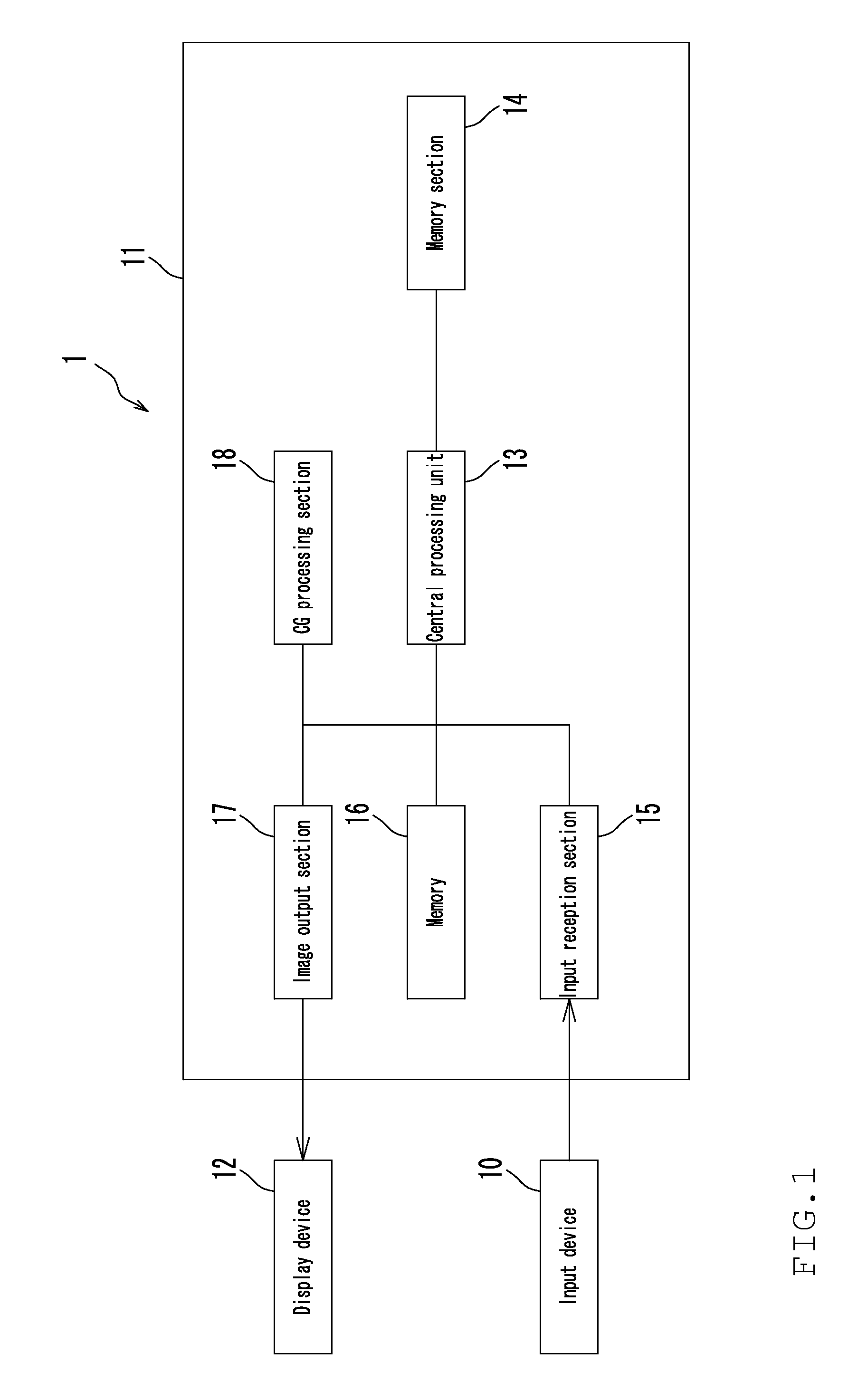
The present invention provides a design support method and system for heat convection fields or mass diffusion fields that reduces the number of times a numerical simulation is required to examine the designing parameters for achieving the design purpose. The method and system include a modeling support step, a mesh generation step, a forward analysis step, a purpose setting step, an inverse analysis step, and a sensitivity display step. The technical effects of the invention include a general-purpose and highly convenient design support system that significantly reduces the number of times of numerical simulation required to examine the designing parameters for achieving the design purpose.

Problems solved by technology

Therefore, in the case where the number of designing variables is large or infinite (distribution amount), it is difficult to realize optimization within a reasonable amount of time.
Such a conventional technique of giving a boundary condition and then obtaining the temperature or the like at a target position (hereinafter, referred to as the “forward problem approach”) is not practical because the numerical simulation needs to be performed too many times until the design purpose is achieved.
For these reasons, there have been no general-purpose design support systems which are easily usable at the site of design.

Method used


Image

  • Design support method, design support system, and design support program for heat convection field
  • Design support method, design support system, and design support program for heat convection field
  • Design support method, design support system, and design support program for heat convection field

Examples


Embodiment Construction

[0036]Hereinafter, preferred embodiments of the present invention will be described in detail with reference to the included drawings.

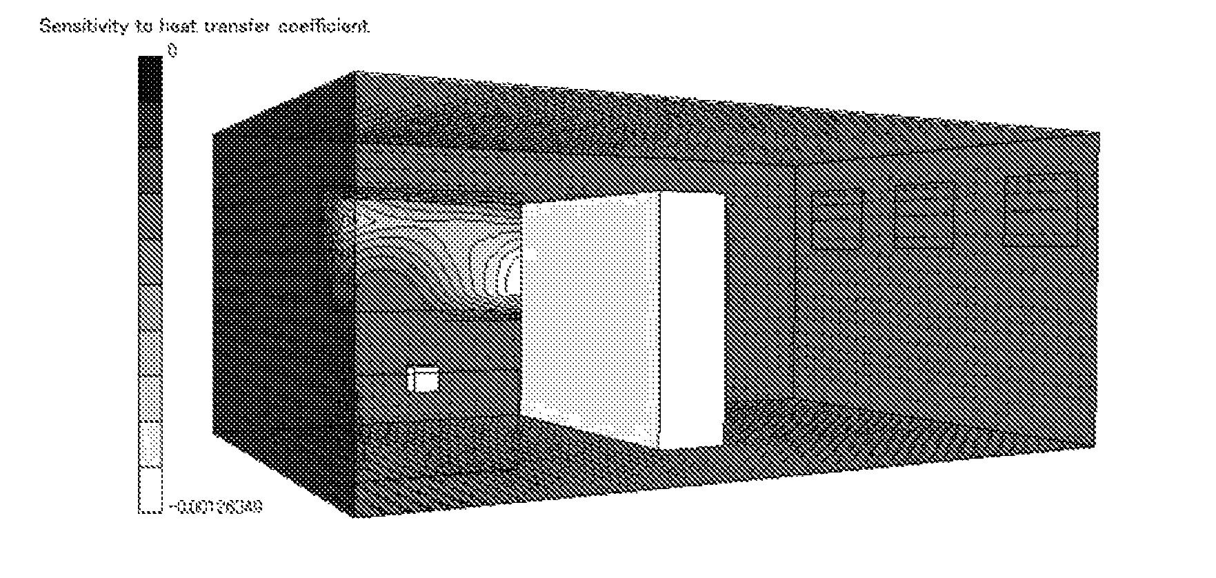
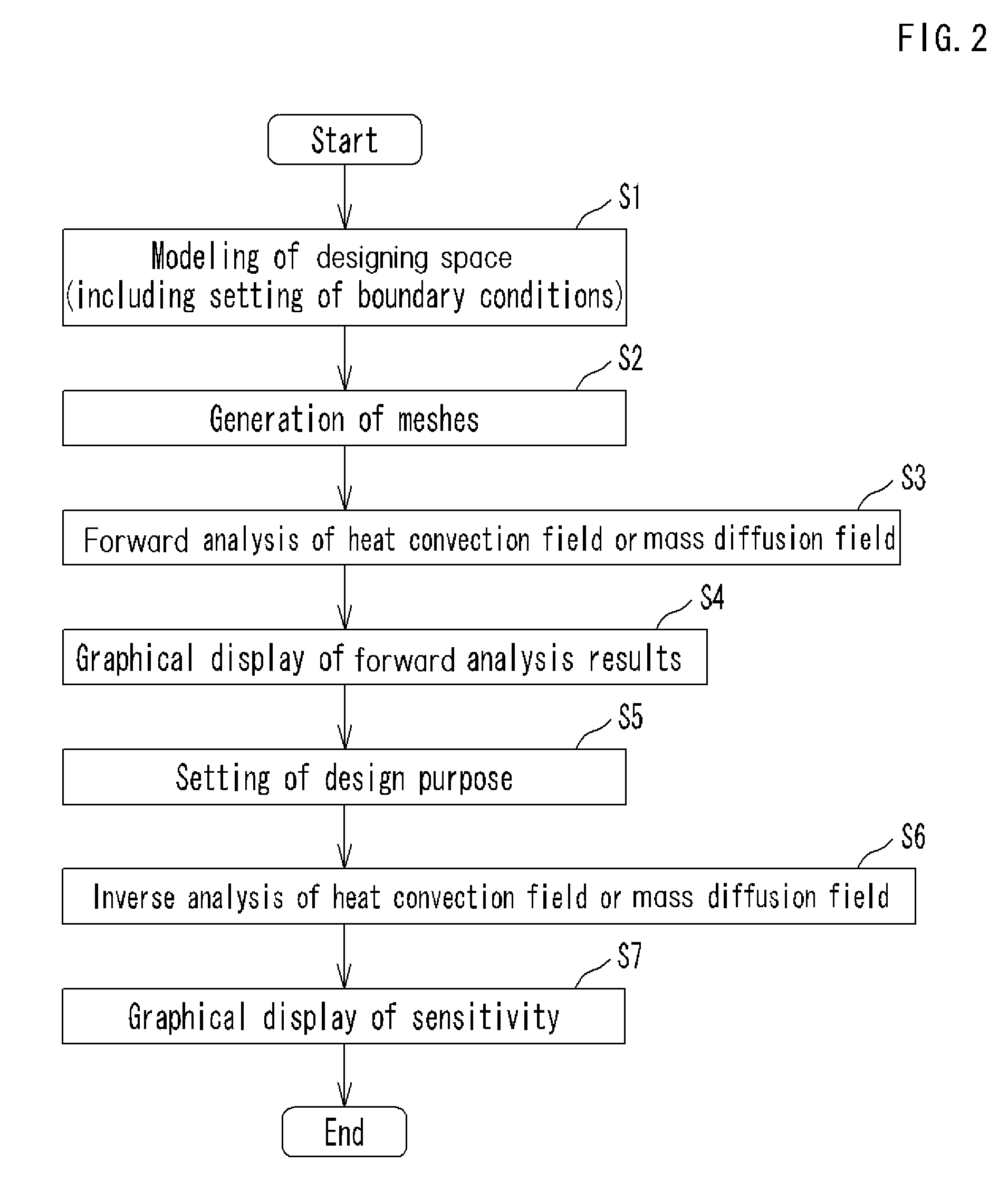
[0037]In one preferred embodiment according to the present invention, numerical analysis, for example, a forward analysis, is performed with predetermined boundary conditions (for example, initially set values of designing parameters). Using the results of the forward analysis, an inverse analysis is performed based on an adjoint numerical analysis. In this way, an analysis of sensitivity for a design purpose is performed. With the adjoint numerical analysis, the sensitivity to any number of designing variables and any distribution designing variable is obtained by performing a numerical analysis once. As a result, a quantitative and visual guide on how to improve the design is obtained. In another preferred embodiment, the result thus obtained is used together with mathematical programming. In this case, it is possible to realize an automatic optimiz...


PUM


Abstract

A highly convenient design support method and design support system for a heat convection field or a mass diffusion field which significantly reduce the number of times of numerical simulation required to examine the designing parameters for achieving the design purpose. The design support method includes a forward analysis step of analyzing the heat convection field or the mass diffusion field by solving an equation of the heat convection field or the mass diffusion field based on an initially set value of a designing parameter, an inverse analysis step of analyzing a sensitivity defined by a change ratio of the design purpose to a designing parameter change by solving an adjoint equation corresponding to the design purpose based on the set design purpose, and a sensitivity display step of displaying information on the sensitivity analyzed by inverse analysis step as a graphic image on the display device.

Description

BACKGROUND OF THE INVENTION[0001]1. Field of the Invention[0002]The present invention relates to a design support method, a design support system, and a design support program for supporting the design of a heat convection field or a mass diffusion field.[0003]2. Description of the Related Art[0004]Design of a heat convection field or a mass diffusion field is required in various sites or uses such as, for example, design of an indoor environment using an air conditioning apparatus, thermal design of electronic devices, and management of exhaust gas concentration in plants.[0005]Along with the recent increase in the operation speed of computers, numerical simulations of a heat convection field or a mass diffusion field have been put into practice, and some general purpose heat and fluid flow analysis software and the like have already become commercially available and are used as designing tools. However, such software is generally used to simply obtain a solution to appropriate par...

Claims


Application Information

Patent Timeline
Patent Type & Authority Patents(United States)
IPC IPC(8): G06G7/56G06G7/48G06G7/57G06F7/60G06F7/64
CPCG06F17/50G06F17/5018G06F2217/16G06F2217/80G06F2111/10G06F2119/08G06F30/00G06F30/23G06F30/17
Inventor MOMOSE, KAZUNARIIKEJIMA, KAORU
Owner OSAKA UNIV
Learn More