
Method and arrangement for measuring timber piece

a timber piece and measurement method technology, applied in the field of measuring timber pieces, can solve the problems of large errors in the calibration result, labour-intensive calibration of the measuring device of the wood handling machine, and errors in the diameter measurement of the trunk of the tree, so as to eliminate random errors, improve accuracy, and facilitate the calibration of the measuring device.

Active Publication Date: 2011-12-06
PONSSE
View PDF16 Cites 2 Cited by
  • Summary
  • Abstract
  • Description
  • Claims
  • Application Information

AI Technical Summary

Benefits of technology

The present invention provides a simple solution to eliminate the drawbacks of the prior art and make calibration of a measuring device easier and more accurate for wood handling machines. The method and arrangement of the invention allow for flexible calibration without interrupting timber harvesting and provide faster and more reliable results. The invention also improves occupational safety and ergonomics by reducing the need for the operator to move between the machine cab and the machine surroundings. The device according to the invention is easy to learn and can be installed in both new and old harvesting machines. The high accuracy of length and diameter measurements is essential for fast and successful value-scaling.

Problems solved by technology

According to the prior art, the measuring device of a wood handling machine is calibrated in a labour-intensive manner using specific calibration scissors and a measuring tape.
First, a sufficiently large lot of trees are cut into timber pieces of a desired length by a wood handling machine in each working area. After this, the operator of the wood handling machine stops the machine and goes to measure the timber pieces, being simultaneously aware of their accurate order on the ground. The length and diameter of the timber pieces included in a calibration sample are typically measured at as many points as necessary, the former by a measuring tape, for example, and the latter by a large slide gauge.
Any deviation of the cross section of the tree trunk to be measured from the ideal circular shape, in particular, and random errors dependent on the person carrying out measurement cause errors in the diameter measurement of tree trunks.
In that case, the calibration result may include considerable errors.
Calibration measurements are also prone to errors because they are usually performed in poor weather and lighting conditions.
The fact that the diameter is to be determined ocularly in a perpendicular direction with respect to the longitudinal axis of the timber piece may easily also cause errors in the diameter result.
However, the real diameter of a timber piece cannot always be measured from below the bark, at least not in daily work, but the proportion of bark in the diameter is evaluated by specific bark parameters based on research.
The accuracy provided by these parameters is naturally limited.
In the length measurement of tree trunks or timber pieces, several other disadvantages also cause measurement errors.
However, this fact is unfortunately often neglected in the prior art.
In other words, when a measuring device is calibrated, the length of the outer surface of a timber piece is often accidentally measured at some point of the timber piece surface.
The surface of a tree trunk is often also faulty, having for example knot stubs, or the timber piece is skewed, which may also cause errors in the measurement result.
In particular, the cut surface sawed to a butt log in felling may easily deviate from the perpendicular direction with respect to the central axis of the tree.
However, as mechanical timber harvesting is becoming more common and introduced into new geographic locations, there will be problems of finding operators who are sufficiently skilled in quality evaluation and able to make quick decisions.

Method used


Image

  • Method and arrangement for measuring timber piece
  • Method and arrangement for measuring timber piece
  • Method and arrangement for measuring timber piece

Examples


Embodiment Construction

Some preferred embodiments of the method and arrangement for measuring a timber piece are described in the following with reference to the above-mentioned figures. In that case, the method and arrangement comprise the components denoted by reference numbers in the figures that correspond to the reference numbers used in this description.

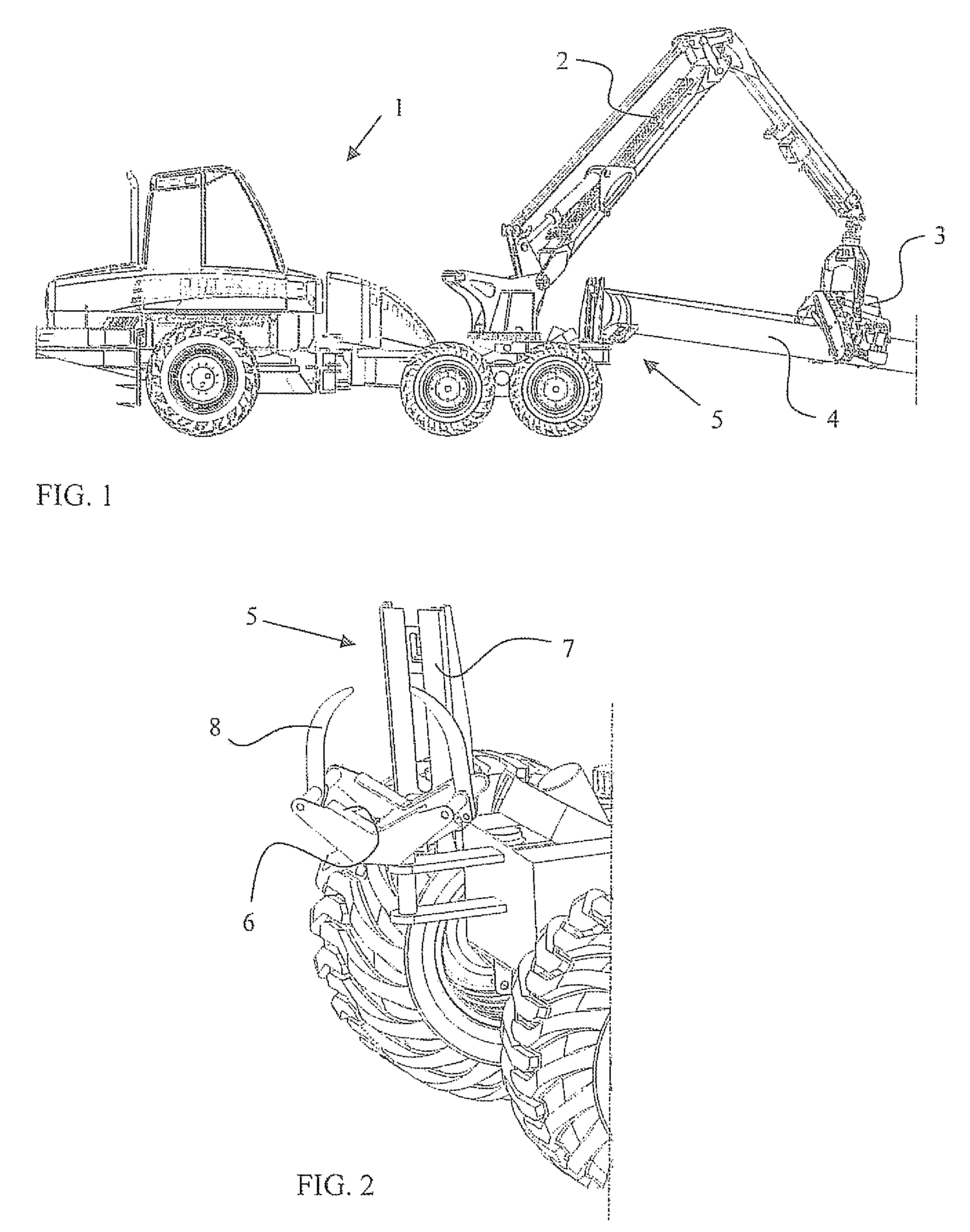
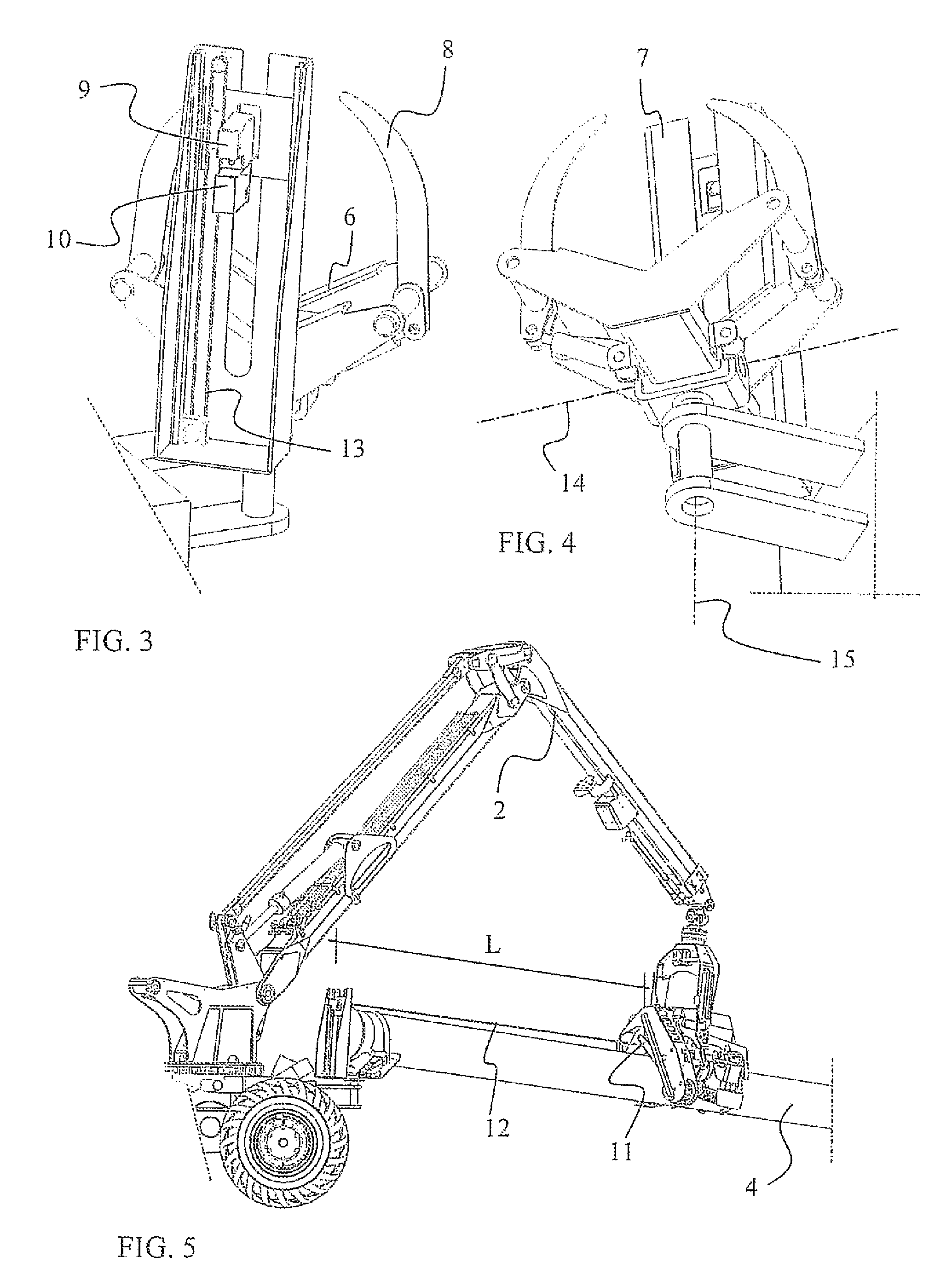
The figures illustrate a wood handling machine 1 comprising a wood handling device movable by booms 2. In this embodiment, this kind of device consists of a harvesting head 3 for felling and handling a tree so as to provide one or more timber pieces 4. Such a harvesting head comprises conventional measuring means for measuring the diameter and length of a timber piece during handling, which are not described in greater detail here.

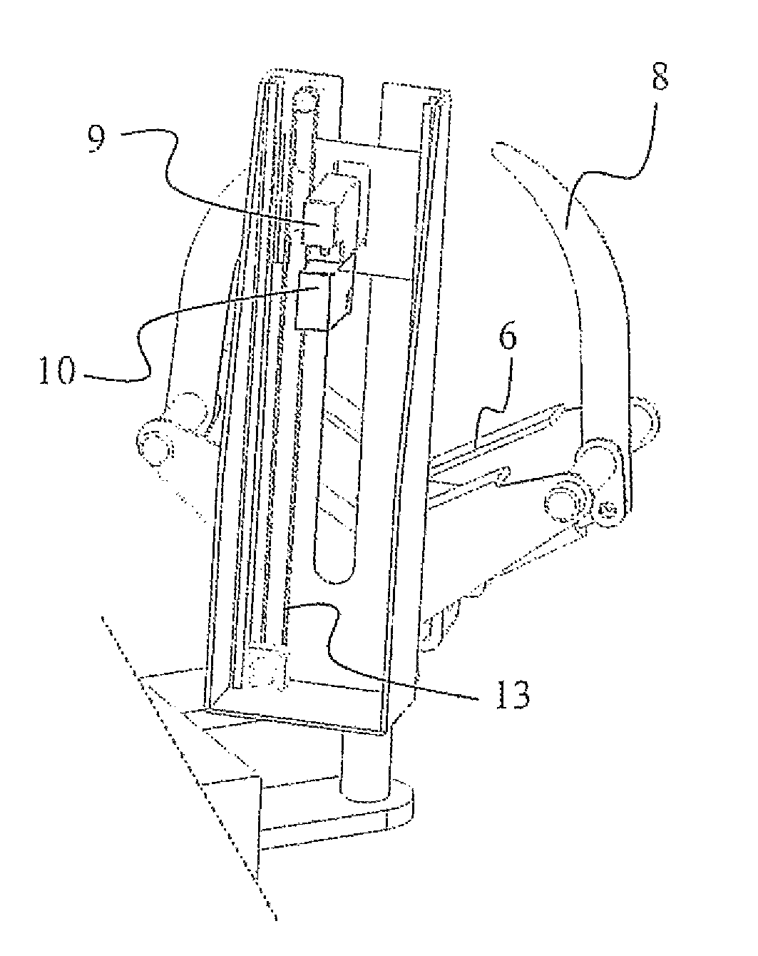
In the present arrangement, the wood handling machine 1 is provided with a measuring carriage 5, consisting of a concave planar surface 6, which is illustrated in greater detail in FIG. 2 and which supports the lower surfac...


PUM


Abstract

The invention relates to a method and arrangement for measuring a timber piece (4) in a wood handling machine (1). Such a wood handling machine comprises booms (2) arranged in a base machine and a wood handling device (3) operating therein. In such a wood handling machine (1), a wood handling device (3) grips the timber piece (4) to be handled, after which one end of the timber piece is guided into a measuring carriage (5) in the wood handling machine by the wood handling device. The timber piece arranged in the measuring carriage is subjected to one or more observation measures by observation means provided in the measuring carriage.

Description

BACKGROUND OF THE INVENTIONThe present invention relates to a method of measuring a timber piece according to the preamble of claim 1.The invention also relates to an arrangement for measuring a timber piece according to the preamble of claim 13.In particular, this kind of method and arrangement are applied to adjusting measurement of a timber piece in a wood handling machine and to calibrating wood measuring devices known per se.In modern mechanical timber harvesting, in particular in timber harvesting according to what is known as “a cut-to-length method”, the demands set on the accuracy of the measurement of timber piece dimensions are constantly increasing. One reason for this is that nowadays most of the timber trade is based on measurement data automatically collected by a wood handling machine. In that case, legislation also lays down certain requirements for the measurement accuracy in timber trade. On the other hand, the benefits of accurate measurement become evident in ti...

Claims


Application Information

Patent Timeline
Patent Type & Authority Patents(United States)
IPC IPC(8): G01B11/00A01G23/08
CPCA01G23/00A01G23/003G01B5/0035A01G23/083G01B21/00
Inventor HAVIMAKI, ESKO
Owner PONSSE
Learn More