
Light-emitting warning device of a safety helmet

a safety helmet and warning device technology, applied in the direction of light support devices, lighting and heating apparatus, fibre light guides, etc., can solve the problems of high cost, high power consumption, inconvenient and not economical use of such safety helmets, and user's safety helmets carrying a greater load

Active Publication Date: 2011-12-06
HO CHANG HSIEN
View PDF8 Cites 28 Cited by
  • Summary
  • Abstract
  • Description
  • Claims
  • Application Information

AI Technical Summary

Benefits of technology

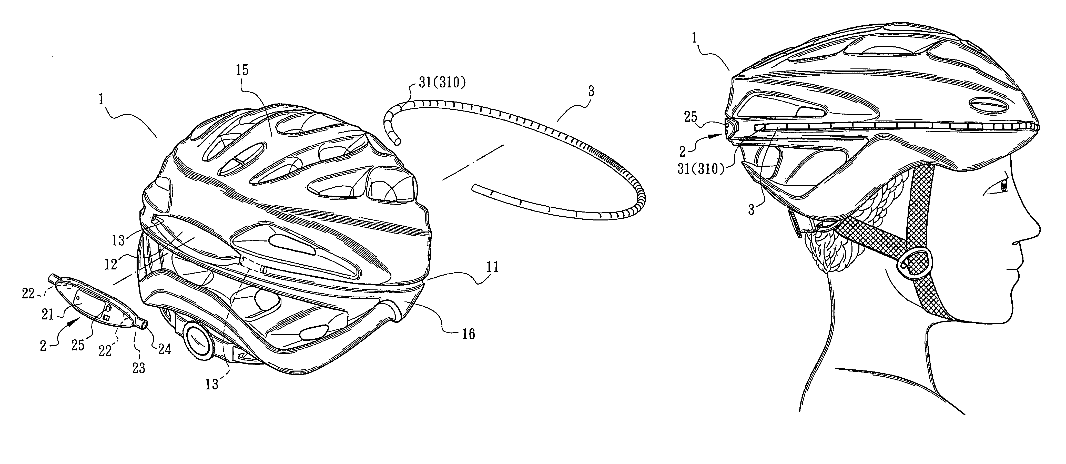
"The present invention is a light-emitting warning device for a safety helmet. It uses a point light source to provide a large range of lighting effect, making it more visible. The device is efficient in emitting light with lower power consumption. The connection sections of the components are positioned in the outer shell of the helmet, protected from water and dust. The light guide element is securely assembled with the helmet and has a longer lifespan. The light guide element is more exposed to the outer side of the helmet, enlarging the light diffusion area. The device includes a helmet main body, a light guide element, and a light source control mechanism. The light source control mechanism has a light source body and an internal cell room for accommodating a cell. The device is connected to the light guide element through hub sections fitted in through holes of the helmet main body. The light source bodies are disposed alongside the inner ends of the hub sections. The technical effects of the invention are improved safety and visibility for the wearer of the safety helmet."

Problems solved by technology

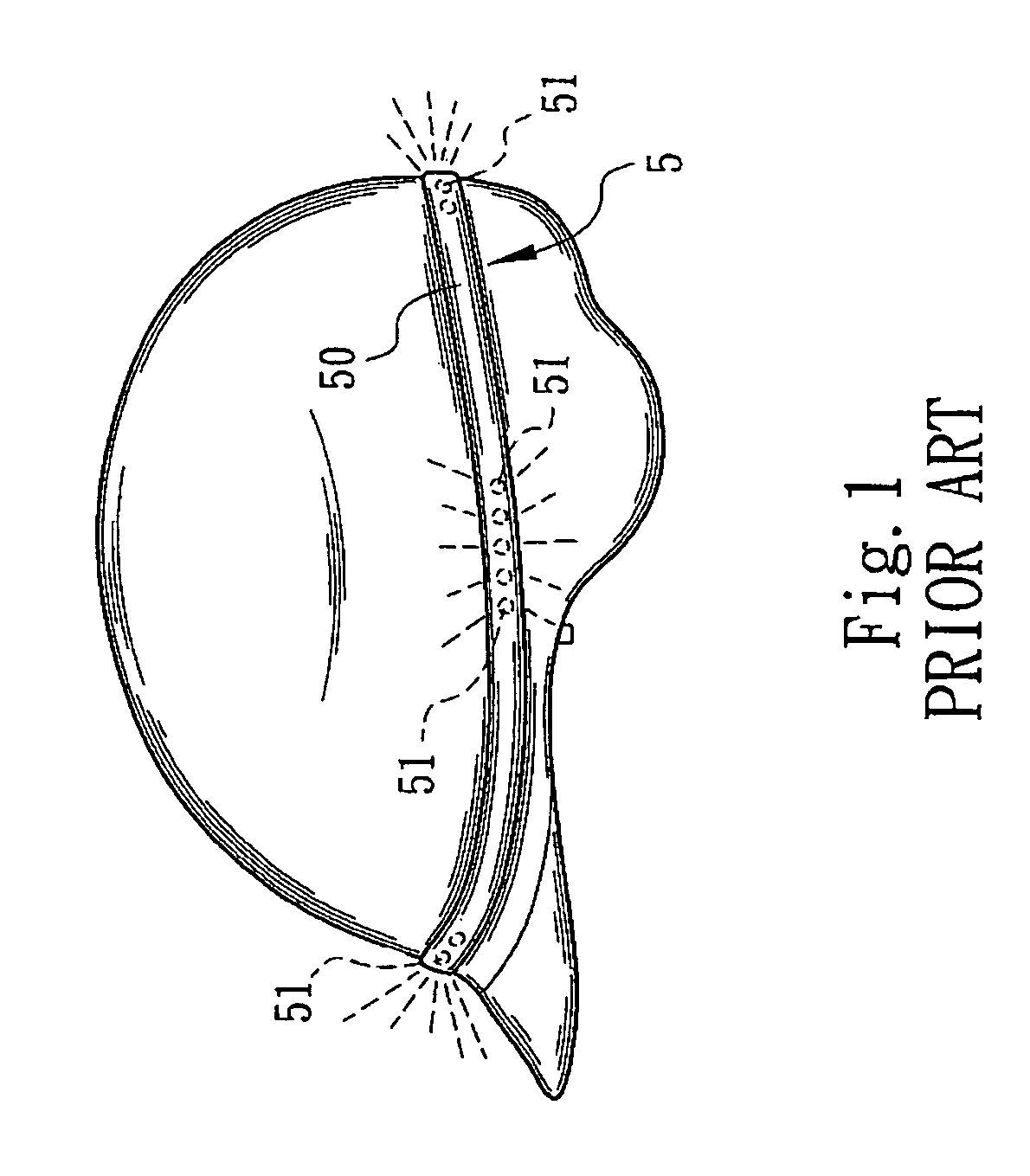
Such warning strip 5 is manufactured at high cost and used with high power consumption.
Moreover, the warning strip 5 has a considerable weight so that a user of the safety helmet will bear greater load.
Therefore, it is inconvenient and not economical to use such safety helmet.
In the case that the number of the warning lights 51 is too small, the lighting range will be insufficient or unapparent.
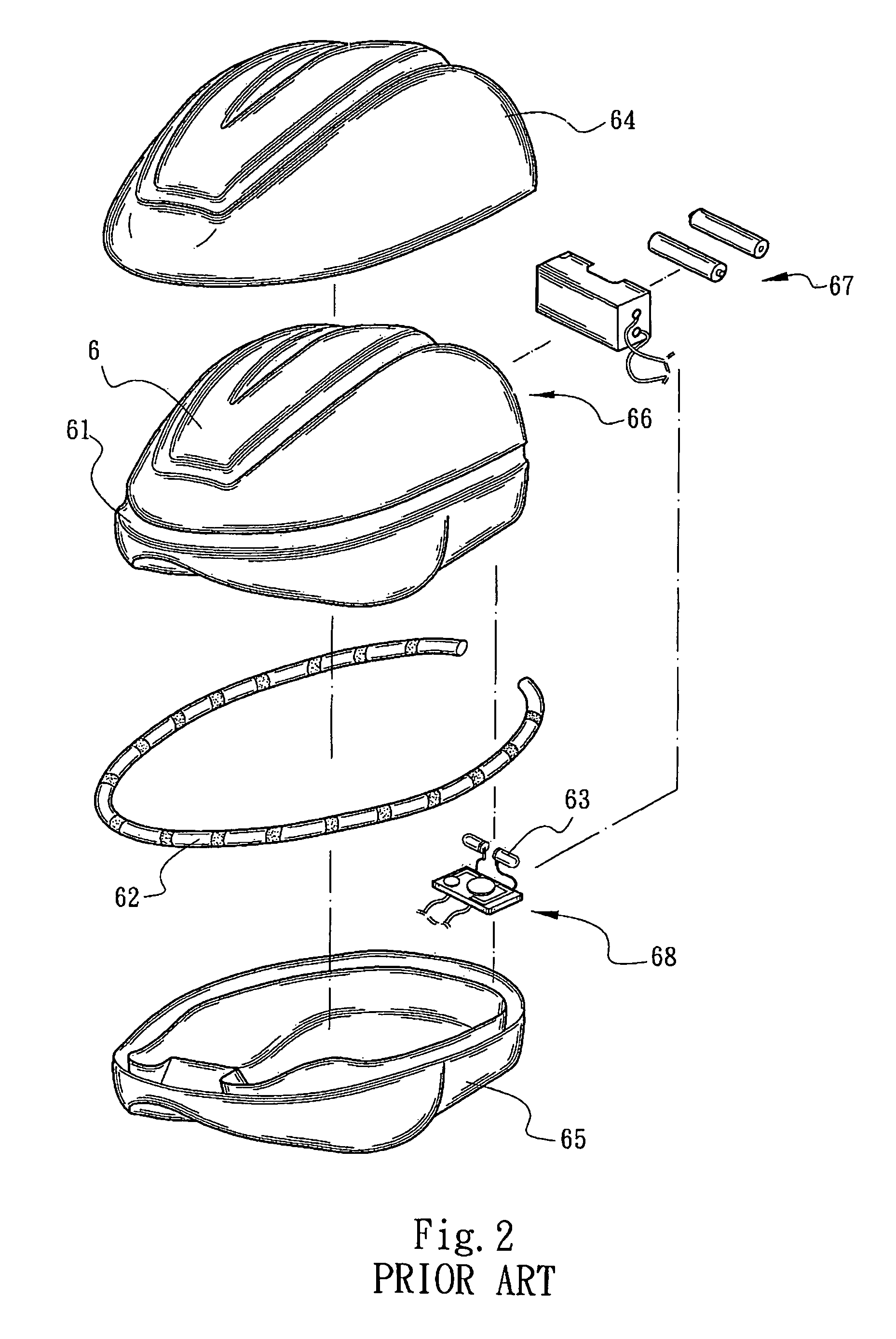
Under such circumstance, the structural strength of the helmet will be deteriorated to affect the safety effect provided by the helmet.
It is quite difficult to assemble the light guide strip 62 with the helmet in this manner so that the manufacturing cost of the helmet is increased and the competitive ability of the product is affected.
As a result, in use, the light guide strip 62 is likely to drop out of the groove 61 and damage or even hit a rider's face or tangle with the rider's neck.
This is extremely dangerous.
However, such measure will inevitably reduce the area of the light guide strip 62 exposed to outer side.
As a result, the intensity and scattering area of the light emitted from the light guide strip 62 will be seriously affected.
Otherwise, after assembled, the recessed channel may be misaligned from the transparent area.
Accordingly, both the poor transparence and the error in the assembling process will affect the light diffusion effect of the fiber optic cable.
As a result, the ratio of defective products will increase due to difficulty in processing.
This will lead to increment of manufacturing cost.

Method used


Image

  • Light-emitting warning device of a safety helmet
  • Light-emitting warning device of a safety helmet
  • Light-emitting warning device of a safety helmet

Examples


Embodiment Construction

[0028]Please refer to FIGS. 3 to 6. The light-emitting warning device of the safety helmet of the present invention includes a helmet main body 1, a light source control mechanism 2 and a light guide element 3. The helmet main body 1 is composed of an outer shell 15 and a foam body 16 formed in the outer shell 15. An annular locating groove 11 is formed on an outer face of the outer shell 15. In addition, a receiving cavity 12 is formed on the helmet main body 1. At least one through hole 13 is formed on the locating groove 11 in communication with an interior of the outer shell 15 or the helmet main body 1. Each of two ends of the locating groove 11 communicates with the receiving cavity 12 via at least one through hole 13 formed in the helmet main body 1. A bottom wall of the locating groove 11 is formed with a plane face 111, which is painted with an adhesive light reflection layer 112. The light source control mechanism 2 is disposed in the receiving cavity 12. The light source ...


PUM


Abstract

A light-emitting warning device of a safety helmet, including a helmet main body, a light guide element and a light source control mechanism. An annular locating groove and a receiving cavity are formed on an outer face of the helmet main body. Two end sections of the locating groove communicate with the receiving cavity via two through holes formed in the helmet main body. An elongated flexible strip body is received in the locating groove. Two end sections of the light guide element extend through the through holes into the receiving cavity to connect with the light source control mechanism. The light source control mechanism projects light into the light guide element, and emits as a lighting ring along the periphery of the helmet main body. The light guide element communicates with an interior of the helmet main body to avoid dropping.

Description

BACKGROUND OF THE INVENTION[0001]The present invention is related to a light-emitting warning device of a safety helmet. The light-emitting warning device is firmly installed and located on an outer face of the safety helmet to emit light at high efficiency within a wide range so as to provide enhanced lighting warning effect.[0002]FIG. 1 shows a conventional safety helmet with a warning strip 5 disposed along a circumference of the safety helmet. The warning strip 5 includes a flexible transparent strip body 50 and multiple warning lights (or LEDs) 51 uniformly distributed in the strip body 50. The warning lights 51 are controlled by a control circuit to light and flicker around the safety helmet so as to provide warning effect in the dark. Such warning strip 5 is manufactured at high cost and used with high power consumption. Therefore, it is necessary to frequently replace the cells. Moreover, the warning strip 5 has a considerable weight so that a user of the safety helmet will ...

Claims


Application Information

Patent Timeline
Patent Type & Authority Patents(United States)
IPC IPC(8): F21V21/084
CPCA42B3/044G02B6/001
Inventor HO, CHANG-HSIEN
Owner HO CHANG HSIEN
Learn More