
Self-cleaning water filter system

Inactive Publication Date: 2011-12-06
GORDON ROBERT
View PDF17 Cites 12 Cited by
  • Summary
  • Abstract
  • Description
  • Claims
  • Application Information

AI Technical Summary

Benefits of technology

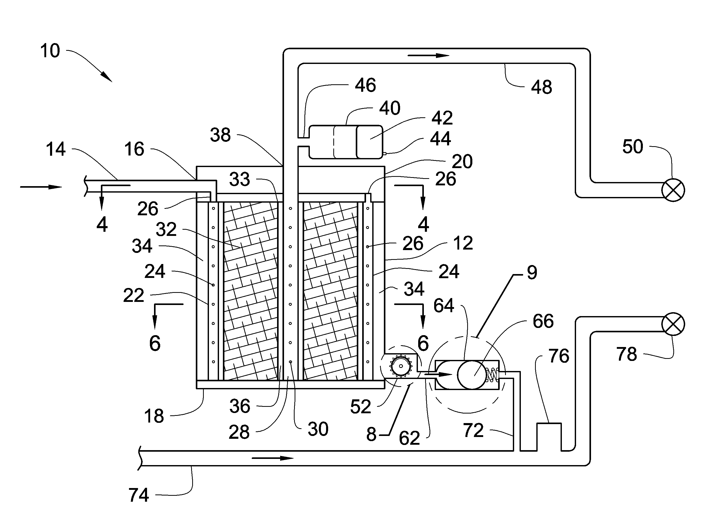
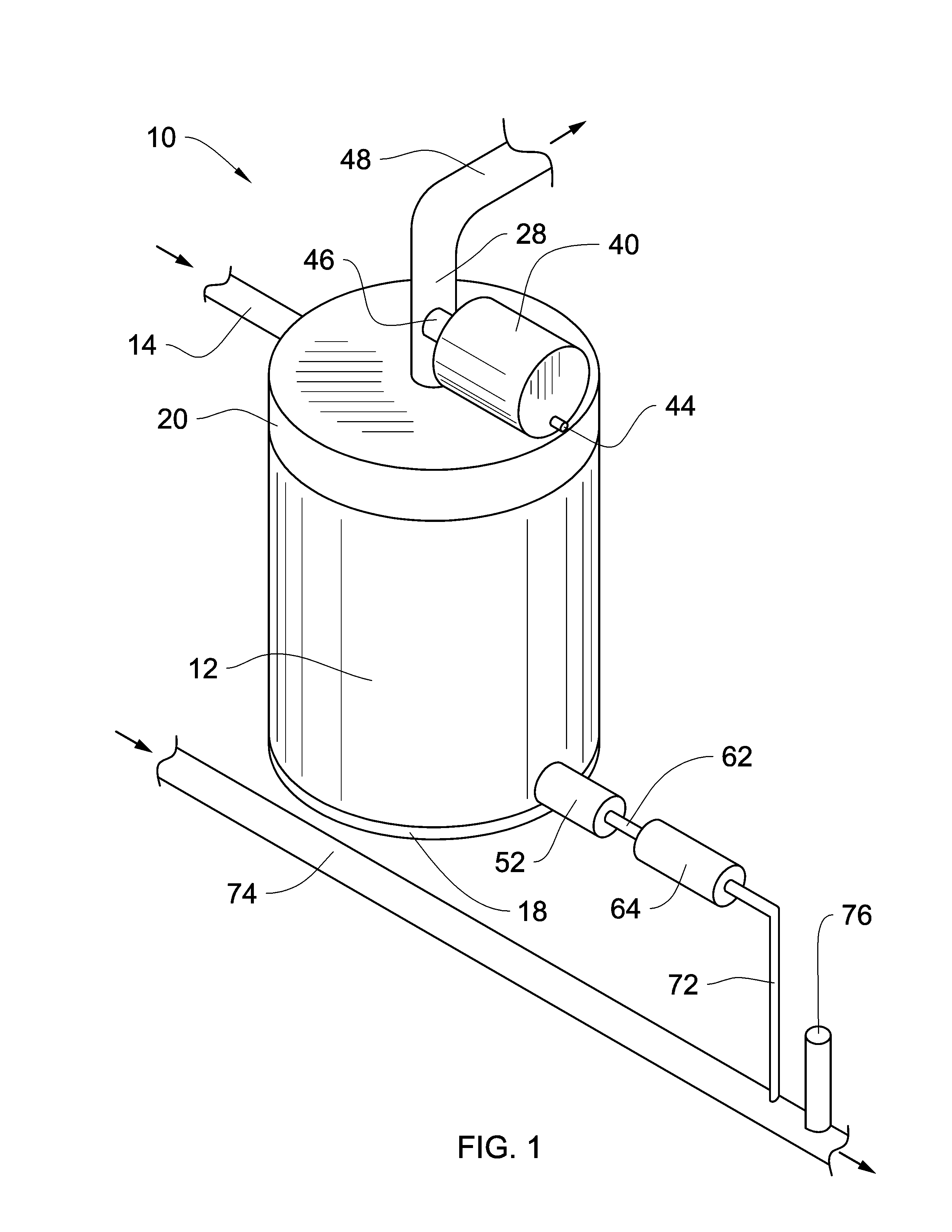
[0013]To attain this, the present invention essentially comprises a self-cleaning water filter system for removing particulate matter from water by producing scouring effect which pulls debris or particles off from a filter element when a fluid flow is produced across the filter element. The self-cleaning water filter system has a filter housing having an upper portion, a lower portion, and an internal cavity. A water inlet tube, an exit tube and a water supply line are adapted to be connected to the filter housing. The filter element is positioned within the filter housing and can have a cylindrical or rectangular configuration. A pressure vessel is in fluid communication with the internal cavity of the filter housing. A pressurizable flexible chamber adapted to expand and contract due to the pressure in the filter housing is positioned inside the pressure vessel. At least one perforated flow tube is positioned in the filter housing adjacent to the filter element and in fluid communication with the pressure vessel.
[0020]It is another object of the present invention to provide a new and improved self-cleaning water filter system that may be easily and efficiently manufactured and marketed.
[0021]An even further object of the present invention is to provide a new and improved self-cleaning water filter system that has a low cost of manufacture with regard to both materials and labor, and which accordingly is then susceptible of low prices of sale to the consuming public, thereby making such self-cleaning water filter system economically available to the buying public.
[0023]Even still another object of the present invention is to provide a self-cleaning water filter system for removing particulate matter from drinking water using a back flushable filter. This allows for an efficient and cost effective water filter system which provides a back flushing process that creates a scouring effect along across the filter element that pulls off debris and particles therefrom.

Problems solved by technology

While the above-described devices fulfill their respective, particular objectives and requirements, the aforementioned patents do not describe a self-cleaning water filter system that allows removing particulate matter from drinking water using a back flushable filter.

Method used


Image

  • Self-cleaning water filter system
  • Self-cleaning water filter system
  • Self-cleaning water filter system

Examples


Embodiment Construction

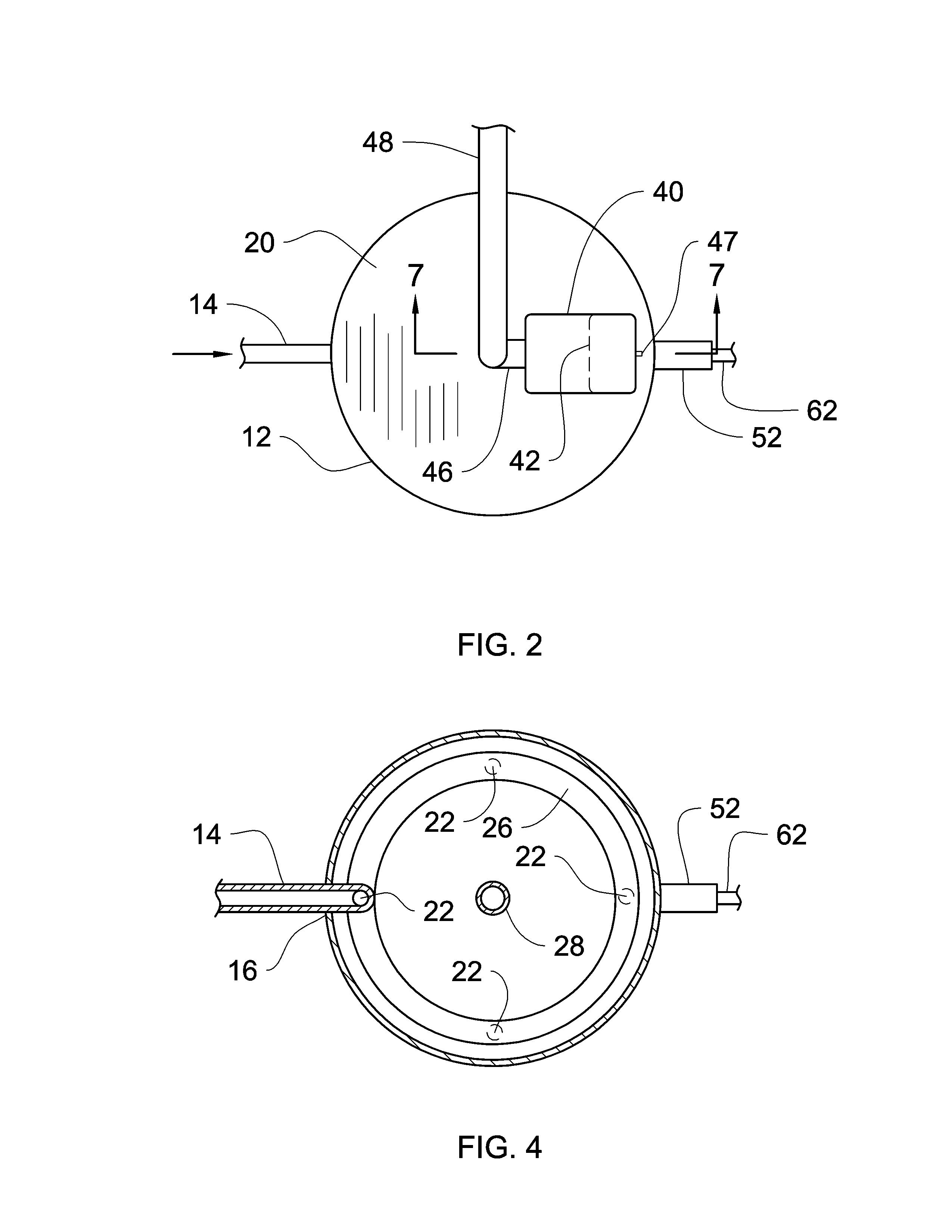
[0042]Referring now to the drawings and particularly to FIGS. 1-14, a preferred embodiment of the self-cleaning water filter system of the present invention is shown and generally designated by the reference numeral 10. The terminology used in the description presented herein is intended to be interpreted in its broadest reasonable manner in accordance with its ordinary use in the art and in accordance with any overt definitions provided below.

[0043]In FIG. 1, a new and improved self-cleaning water filter system 10 of the present invention for removing particulate matter from drinking water using a back flushable filter system is illustrated and will be described. The self-cleaning water filter system 10 may be mounted under a kitchen sink or any hot / cold water line source. More particularly, the self-cleaning water filter system 10 has a filter housing 12 having a bottom plate 18, and a manifold 20. The filter housing 12 has a generally cylindrical configuration featuring an intern...


PUM

PropertyMeasurementUnit
Pressureaaaaaaaaaa
Flow rateaaaaaaaaaa

Abstract

A self-cleaning water filter system for removing particulate matter from water by producing scouring effect which pulls debris or particles off from a filter element when a fluid flow is produced across the filter element. The self-cleaning water filter system has a filter housing having an upper portion, a lower portion, and an internal cavity. A water inlet tube, an exit tube and a water supply line are adapted to be connected to the filter housing. The filter element is positioned within the filter housing and can have a cylindrical or rectangular configuration. A pressure vessel is in fluid communication with the internal cavity of the filter housing. A pressurizable flexible chamber adapted to expand and contract due to the pressure in the filter housing is positioned inside the pressure vessel. At least one perforated flow tube is positioned in the filter housing adjacent to the filter element and in fluid communication with the pressure vessel.

Description

CROSS-REFERENCE TO RELATED APPLICATION[0001]Not applicableFEDERALLY SPONSORED RESEARCH[0002]Not applicableSEQUENCE LISTING OR PROGRAM[0003]Not applicableBACKGROUND OF THE INVENTION[0004]1. Field of the Invention[0005]The self-cleaning water filter system has particular utility in connection with removing particulate matter from drinking water using a back flushable filter system.[0006]2. Description of the Prior Art[0007]Self-cleaning water filter systems are desirable filtering drinking water and for providing an affective way to removing particulate matter from drinking water while at the same time provide an efficient and easy system to clean the filter system.[0008]The use of water filters is known in the prior art. For example: U.S. Pat. No. 4,037,661; U.S. Pat. No. 4,169,792; U.S. Pat. No. 4,210,539; U.S. Pat. No. 5,228,993; U.S. Pat. No. 5,490,924; U.S. Pat. No. 5,690,824; U.S. Pat. No. 5,910,249; U.S. Pat. No. 6,231,764; U.S. Pat. No. 6,283,305; and Great Britain Patent Numb...

Claims


Application Information

Patent Timeline
IPC IPC(8): B01D29/66
CPCB01D29/114B01D29/66B01D29/72B01D29/908
Inventor GORDON, ROBERT
Owner GORDON ROBERT
Learn More