
Characterizing vision systems

a vision system and characterization technology, applied in the field of machine vision, can solve the problems of difficult for a vision system integrator to physically mimic all, unfavorable brute force testing of the system under all conditions, and increase the number of variations and combinations possible, so as to improve the performance and reliability of the vision system, and the robustness and reliability of the machine vision system

Active Publication Date: 2011-11-29
NATIONAL INSTRUMENTS
View PDF4 Cites 2 Cited by
  • Summary
  • Abstract
  • Description
  • Claims
  • Application Information

AI Technical Summary

Benefits of technology

The patent describes a system and method for characterizing vision systems by creating a multi-dimensional space that describes the conditions under which the vision system operates. This space is divided into different dimensions, with each dimension representing a different condition that affects the vision system. The system uses a GUI to allow users to specify the bounds of the condition space and the number of samples needed for testing. The system then samples the condition space using a pseudo-random sequence to determine the test conditions under which the vision system will inspect an image. These test conditions include parameters for each axis of the condition space. The system then performs a vision inspection on each test image and generates results based on the test conditions. The system can also modify the vision system to create different test conditions and perform the vision inspections simultaneously. The technical effect of this system is to provide a comprehensive and robust way to characterize the performance of vision systems.

Problems solved by technology

However, theoretical or ideal conditions under which a vision system may be specified may be quite different from actual or field conditions under which the vision system operates in practice, i.e., in the real world.
However, the number of variations and combinations possible increases dramatically with the number of parameters, and so a brute force approach to testing the system under all conditions is not feasible.
In reality it is very difficult for a vision system integrator to physically mimic all the variations that can take place on the production line.
Prior art analysis and characterization of vision systems has typically been limited to testing the system according to a uniform sampling of each dimension of a condition space independently, which ignores synergistic effects among the parameters.
Higher dimensional condition spaces, e.g., 2 or more dimensions, have not heretofore been analyzed for characterization of vision systems, primarily due to the rapid increases in complexity and commensurate computational resources required.

Method used


Image

  • Characterizing vision systems
  • Characterizing vision systems
  • Characterizing vision systems

Examples


example case

[0143]The following presents an exemplary simple case according to one embodiment, where the above method is applied to line detection. In this example, the machine vision inspection involves the detection of the perforation line in a paper towel using an edge detection algorithm. In this particular application, the imaging assumes that the power towel under inspection can undergo some rotation; there may be some motion blur and the presence of noise in the image.

[0144]FIG. 12 illustrates an image of the paper towel, where, as indicated above, the inspection process is to determine the perforation, which in this case is a vertical line. As FIG. 12 shows, the conditions or tolerances under which this image was “taken”, or, more accurately, simulated, are + / −5 degrees rotation, motion blur of 15 pixels, and 100% noise. In other words, the condition space spans rotation from −5 degrees to +5 degrees, motion blur from 0 to 15 pixels, and noise levels from 0 to 100%. Note that in this si...


PUM


Abstract

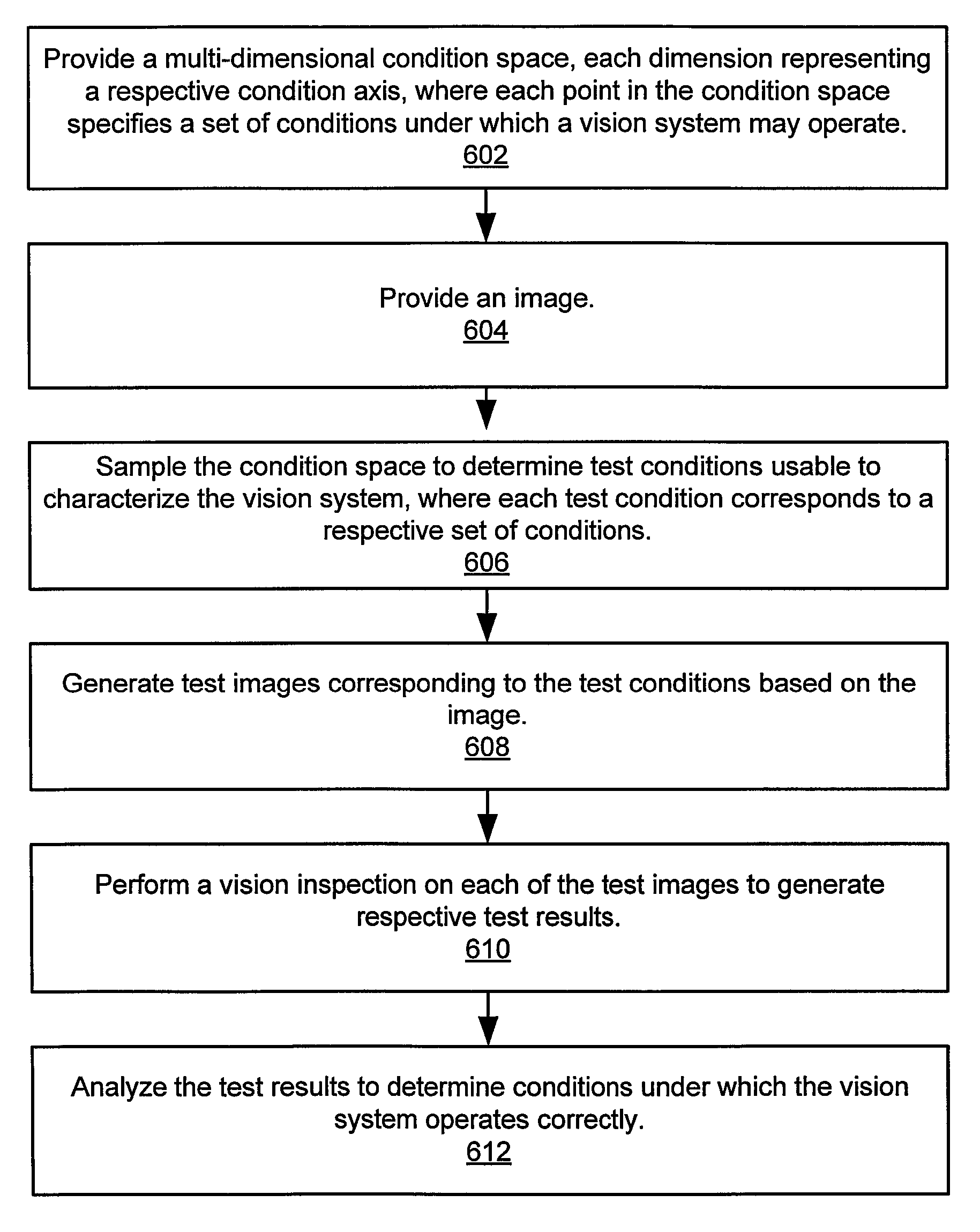
System and method for characterizing vision systems. A multi-dimensional condition space is provided, each dimension representing a respective condition axis, where each point in the condition space specifies a set of conditions under which a vision system may operate. An image is provided. The condition space is sampled according to a pseudo-random sequence, e.g., a low-discrepancy sequence, to determine a plurality of test conditions usable to characterize the vision system, where each test condition corresponds to a respective set of conditions. A plurality of test images corresponding to the plurality of test conditions are generated based on the image, e.g., by applying image processing functions to the image that simulate the test conditions. A vision inspection is performed on each of the plurality of test images to generate respective test results, and the test results are analyzed to determine conditions under which the vision system operates correctly.

Description

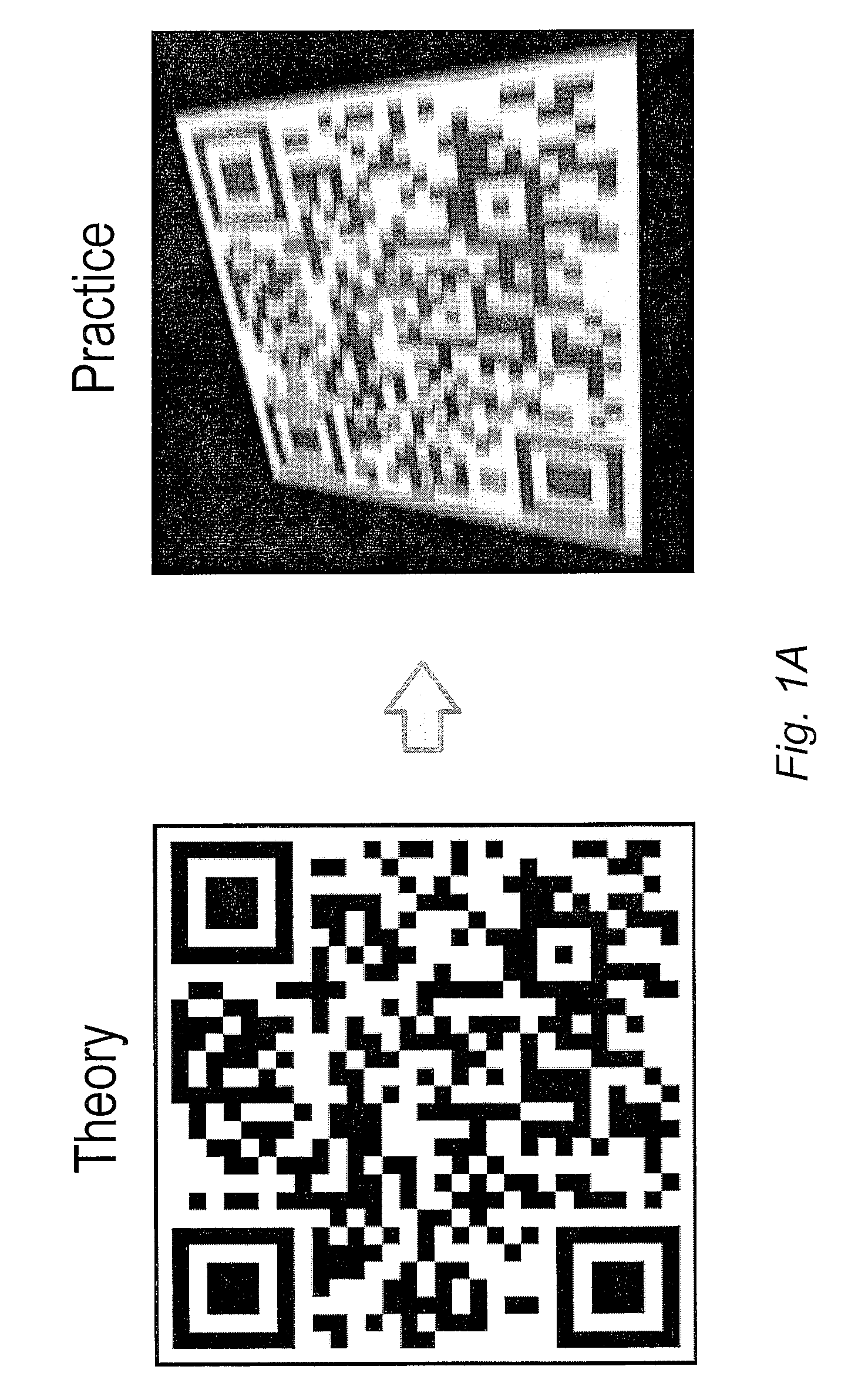
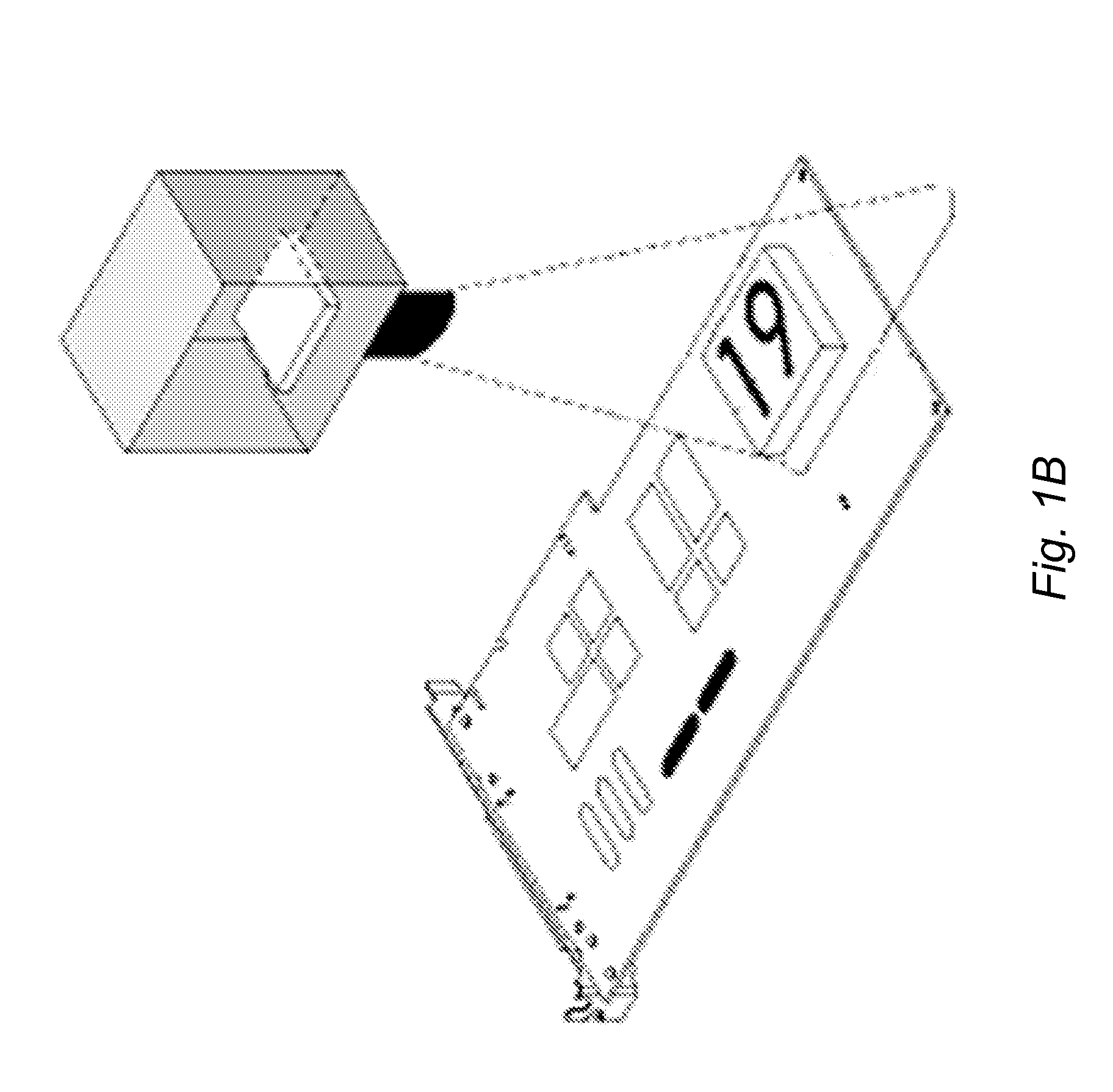
FIELD OF THE INVENTION[0001]The present invention relates to the machine vision, and more particularly to a system and method for characterizing vision systems.DESCRIPTION OF THE RELATED ART[0002]Machine vision is an increasingly important technology in many areas of endeavor, such as manufacturing, quality control, security, and research, among others. However, theoretical or ideal conditions under which a vision system may be specified may be quite different from actual or field conditions under which the vision system operates in practice, i.e., in the real world.[0003]This fact is illustrated in FIG. 1A, which shows an idealized image (left) and a more realistic example of an image from practice (right), according to the prior art. As may be seen, the “practice” image is influenced by various conditions (including vision system parameters) that are not a factor in the “theory” image. For example, FIG. 1B illustrates an exemplary vision system examining a circuit board. The perfo...

Claims


Application Information

Patent Timeline
Patent Type & Authority Patents(United States)
IPC IPC(8): G06K9/00
CPCG01N21/8806
Inventor NAIR, DINESH R.VAZQUEZ, NICOLASGIESEN, ROBERT J. B.KEELER, JOSHUA B.SMYTH, BRUCE
Owner NATIONAL INSTRUMENTS
Learn More