Electrophoretic display apparatus and driving method thereof

a display apparatus and electrophoretic technology, applied in the field of display apparatuses, can solve the problems of reducing the life of the display apparatus and a contrast, unable to obtain predetermined gradation optical level, and consequently applying dc voltage to the display device for a long time, so as to prevent the accumulation of residual dc components

Inactive Publication Date: 2011-11-29
CANON KK
View PDF16 Cites 6 Cited by
  • Summary
  • Abstract
  • Description
  • Claims
  • Application Information

AI Technical Summary

Benefits of technology

[0008]An object of the present invention is to provide an electrophoretic display apparatus capable of repetitively effecting stable display.
[0040]According to the present invention, as the migration particles, those of two types which have mutually different charge polarities and a substantially identical color are used, so that it becomes possible to drive the electrophoretic display apparatus by an AC voltage. Further, by alternately applying a display voltage of a predetermined polarity and a display electrode of a polarity opposite to the predetermined polarity to the display electrode for changing the distribution of the migration particles to effect display, even when the display or rewriting of the display is repetitively performed, it is possible to prevent accumulating of residual DC component to perform stable display repetitively.

Problems solved by technology

In such an electrophoretic display apparatus, however, there has arisen a problem such that a life of the display apparatus and a contrast are lowered due to inclusion of the coloring agent such as a dye.
However, when such display rewriting is repeated many times, the DC voltage is consequently applied to the display device for a long time in some cases.
As a result, the voltage applied to the migration particles fluctuates, so that there arises such a problem of display burn-in that a predetermined gradation optical level cannot be obtained.

Method used


Image

  • Electrophoretic display apparatus and driving method thereof
  • Electrophoretic display apparatus and driving method thereof
  • Electrophoretic display apparatus and driving method thereof

Examples


example 1

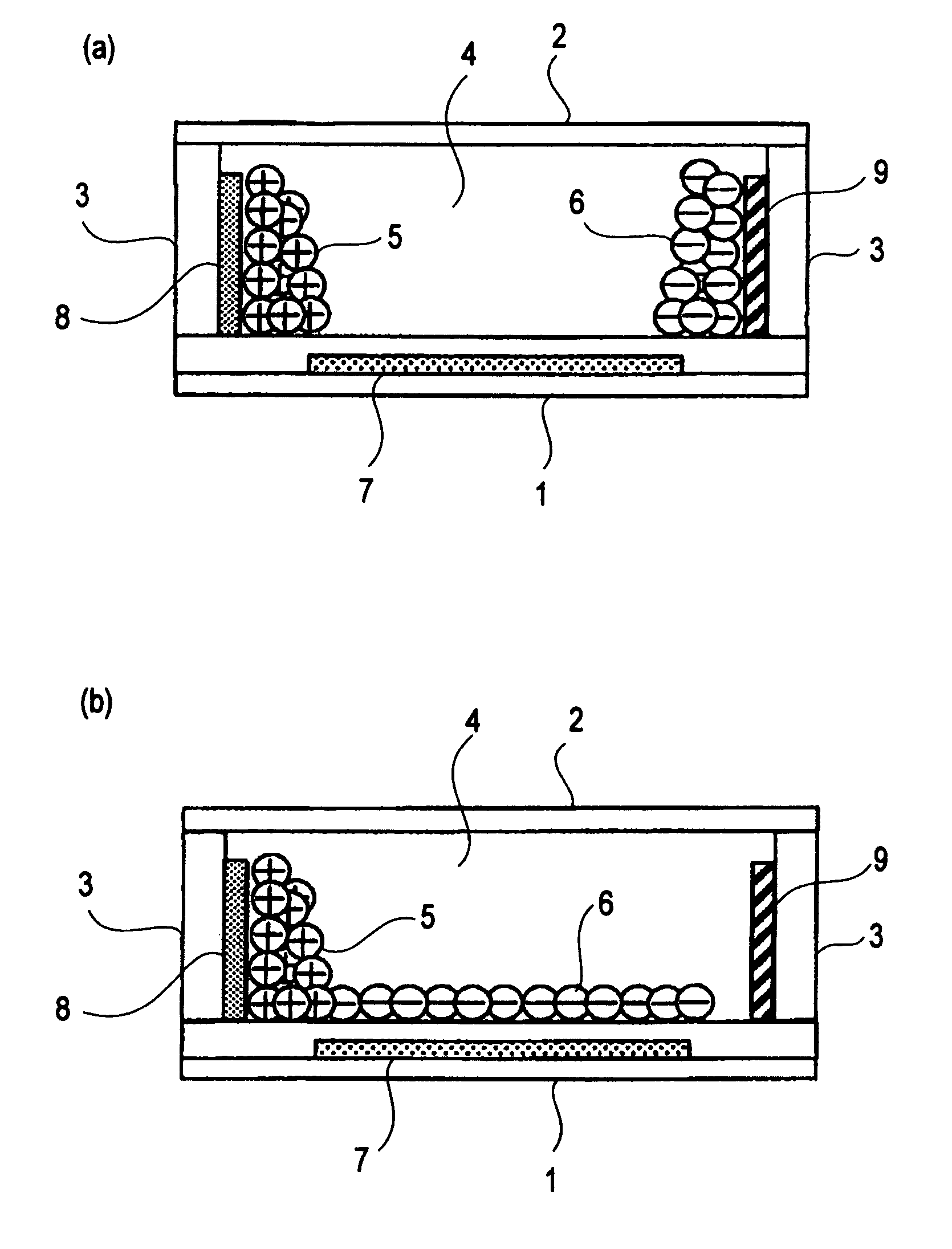
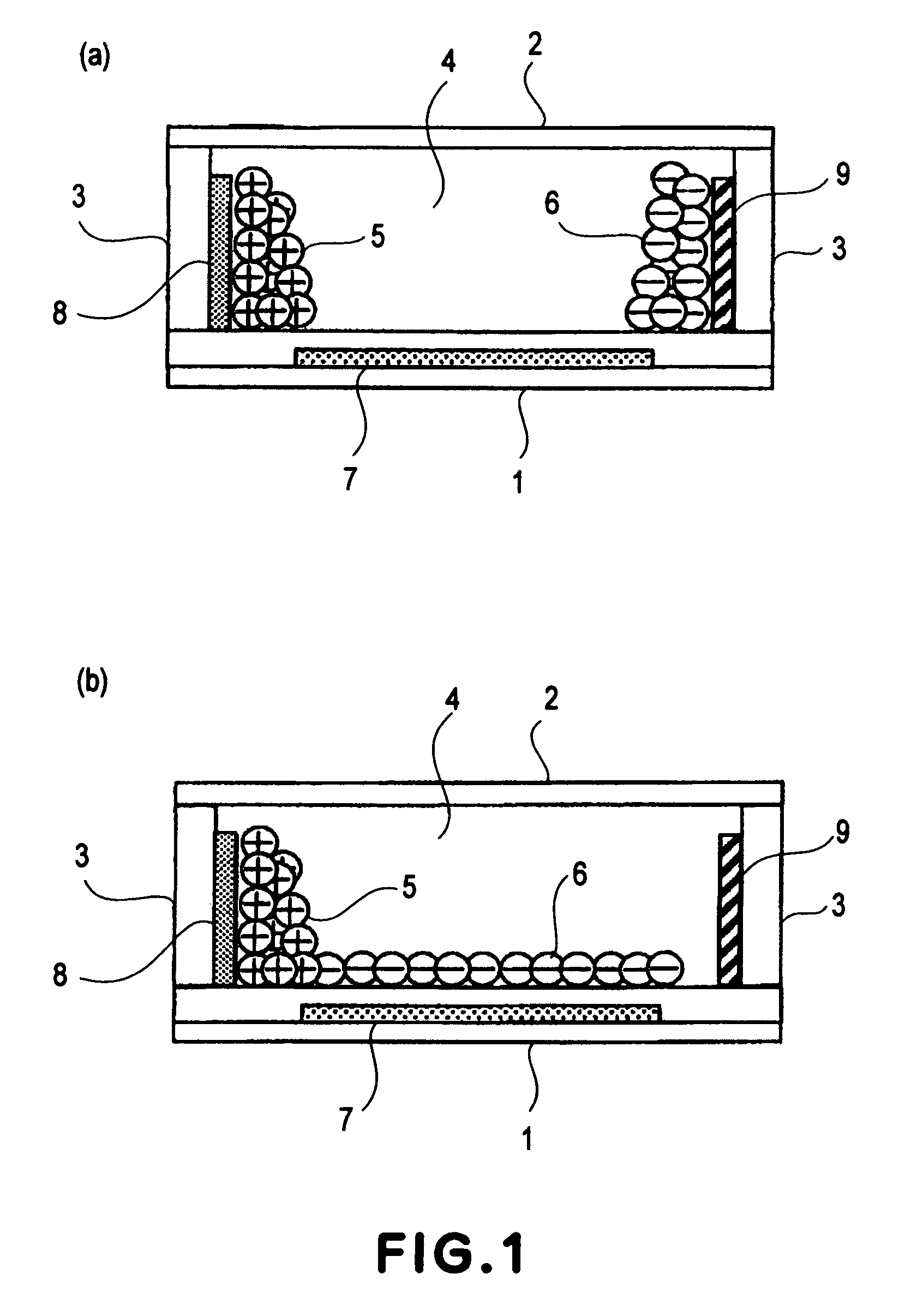
[0111]In this example, an electrophoretic display apparatus including the electrophoretic display device shown in FIGS. 1(a) and 1(b) according to First Embodiment of the present invention is prepared in the following manner. The electrophoretic display device includes a matrix panel having 600×1800 pixels. Further, each of the pixels has a rectangular planar shape as shown in FIG. 7 and has a size of 40 μm (width)×120μ (length).

[0112]On a 1.1 mm-thick glass substrate as a first substrate 1, a thin film transistor (TFT) (not shown) and an IC (not shown), and other wirings necessary for drive are formed and thereon, an Si3N4 film as an insulating film is formed at the entire surface of the first substrate 1. Then, an Al layer is formed and subjected to patterning to form a first electrode 7. Incidentally, the first electrode 7 is communicated with the TFT through a contact hole which has been formed in advance.

[0113]Next, after the first electrode 7 is formed, a white (coloring) laye...

example 2

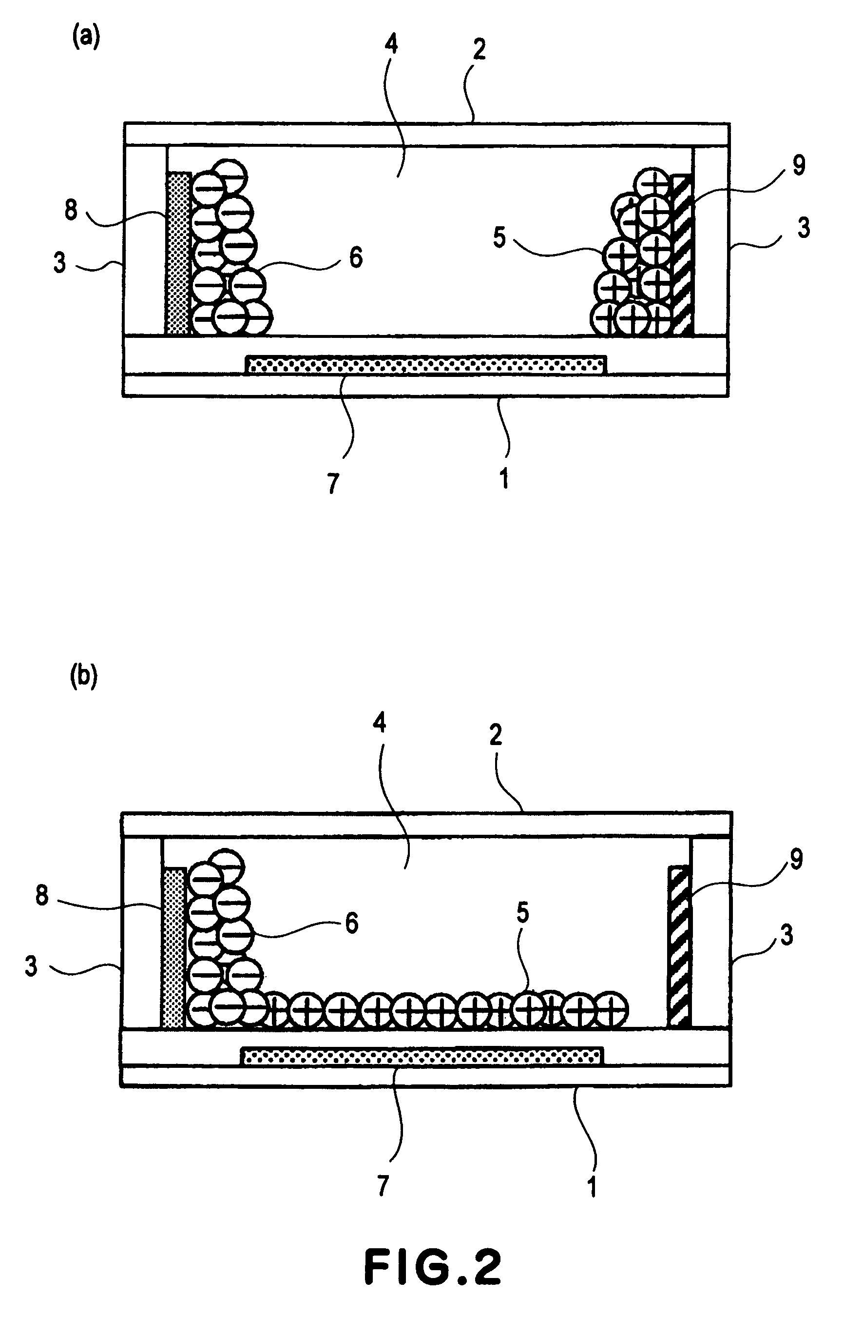
[0128]In this example, an electrophoretic display apparatus including the electrophoretic display device shown in FIGS. 5(a) and 5(b) is prepared in the following manner. The electrophoretic display device includes a matrix panel having 600×1800 pixels. Further, each of the pixels has a rectangular planar shape as shown in FIG. 9 and has a size of 40 μm (width)×120μ (length). In this example, electrodes include a first electrode 71 and a second electrode 81 as described above.

[0129]On a 1.1 mm-thick glass substrate as a first substrate 1, a thin film transistor (TFT) (not shown) and an IC (not shown), and other wirings necessary for drive are formed and thereon, an Si3N4 film as an insulating film is formed at the entire surface of the first substrate 1. Then, an Al layer is formed and subjected to patterning to form a first electrode 71. Incidentally, the first electrode 71 is communicated with the TFT through a contact hole which has been formed in advance.

[0130]Further, a surface...

example 3

[0148]In this example, an electrophoretic display apparatus is prepared and subjected to the display operations in the same manner as in Example 2.

[0149]A driving method of the tested matrix panel will be described with reference to FIGS. 11(a) and 11(b).

[0150]Also in this example, display rewriting is performed in such a manner that the display operation shown in FIG. 10(a) and the display operation shown in FIG. 10(b) are alternatively repeated. More specifically, in this example, every two adjacent pixels, the first display operation and the second display operation are repetitively performed alternately while performing the reset operation between the display operations shown in FIGS. 8(a) and 8(b). In this driving method, a polarity of voltage applied is changed for each adjacent pixel. Accordingly, this driving method is referred to as a “dot inversion driving method”.

[0151]The electrophoretic display apparatus in this example has a memory characteristic with respect to a disp...


PUM

PropertyMeasurementUnit
voltageaaaaaaaaaa
voltageaaaaaaaaaa
voltageaaaaaaaaaa

Abstract

A display apparatus includes a first substrate provided with a closed container, two types of charged particles held in the closed container and having mutually different charge polarities and a substantially identical color, and first, second and third electrodes for generating an electric field in the closed container, with the third electrode being disposed on the first substrate. The display apparatus alternately executes a first display operation and a second display operation, wherein in the first display operation, the charged particles create a first distribution on a first electrode side by changing a voltage applied to the second electrode or the third electrode after a first reset operation in which the charged particles create a second distribution on a second electrode side and on a third electrode side by applying a first voltage to the second electrode and to the third electrode. In the second display operation, the charged particles create a third distribution on the first electrode side by changing a voltage applied to the second electrode or the third electrode after a second reset operation in which the charged particles create a fourth distribution, substantially identical to the second distribution, on the second electrode side and on the third electrode side by applying a second voltage, opposite in polarity to the first voltage, to the second electrode and to the third electrode.

Description

TECHNICAL FIELD[0001]The present invention relates to a display apparatus, such as an electrophoretic display apparatus which effects display on the basis of movement of (electrophoretic) migration particles, and a driving method of the electrophoretic display apparatus.BACKGROUND ART[0002]In recent years, an amount of information which an individual can deal with has been significantly measured due to a remarkable advance of digital technology. In connection with this, development of display as information output means has been performed actively, so that technological innovation for displays of high usabilities, such as high definition, low power consumption, light weight, thin shape, etc., has been continued. Particularly, in recent times, a high-definition display which is easy to read and has a display quality equivalent to printed matter has been desired. The display of this type is a technique indispensable to a next-generation product, such as electronic paper, electronic bo...

Claims


Application Information

Patent Timeline
Patent Type & Authority Patents(United States)
IPC IPC(8): G09G3/34G02F1/167G09G3/20
CPCG02F1/167G02F2201/12G02F1/16762G02F1/1681
Inventor MATSUDA, YOJIRO
Owner CANON KK
Why Eureka
Try Eureka