
Sheet conveyance apparatus

a technology of conveyancing apparatus and sheet, which is applied in the direction of registering device, thin material processing, article separation, etc., can solve the problems of lateral misalignment, high cost, and long time to return the sensor to its original position

Active Publication Date: 2011-11-29
CANON KK
View PDF12 Cites 11 Cited by
  • Summary
  • Abstract
  • Description
  • Claims
  • Application Information

AI Technical Summary

Benefits of technology

The present invention provides a sheet conveyance apparatus that can quickly detect the end of a sheet of paper, even when the sheets are conveyed at a high speed. This allows for faster alignment and improved productivity. The apparatus includes a sensor unit that detects the sheet end, a drive unit that moves the sensor unit to the position where the sheet end is detected, and a control method that determines the direction in which the sensor unit should move and controls it accordingly. The invention also provides an image forming apparatus and a sheet processing apparatus that use the sheet conveyance apparatus. A computer-readable program is also provided to allow for computer execution of the control method. Overall, the invention enables quicker and more accurate detection of sheet ends, leading to improved production efficiency.

Problems solved by technology

However, with the increase in apparatus size and with the increase in types of sheet processing apparatuses used in combination with the image forming apparatus, a lateral misalignment of a sheet is liable to occur in the post-processing apparatus disposed downstream of the image forming apparatus.
However, with the increase in amount of lateral misalignment, the sheet side end is at a location more away from the sensor.
Thus, the sensor must be moved for a longer distance to detect the sheet side end, and it takes much time to return the sensor to its original position after the sheet end detection.
As a result, if the sheet is conveyed at high speed, the sheet side end cannot be detected in time, and the sensor cannot be returned to its original position before arrival of the next sheet.
To obviate this, the sheet conveyance speed must be lowered or the sheet conveyance interval must be increased, posing a problem of reduction in productivity (sheet processing number per unit time).

Method used


Image

  • Sheet conveyance apparatus
  • Sheet conveyance apparatus
  • Sheet conveyance apparatus

Examples


Embodiment Construction

[0030]The present invention will now be described in detail below with reference to the drawings showing a preferred embodiment thereof.

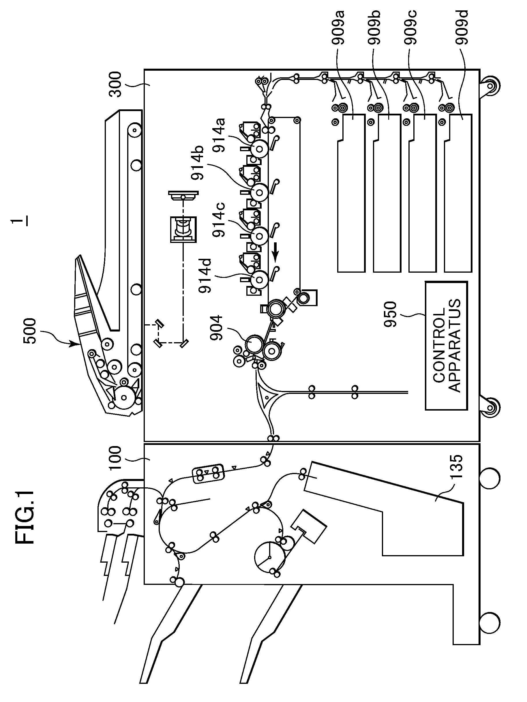
[0031]FIG. 1 schematically shows in vertical cross section the construction of an image forming system including an image forming apparatus and a sheet processing apparatus having a sheet conveyance apparatus according to one embodiment of this invention.

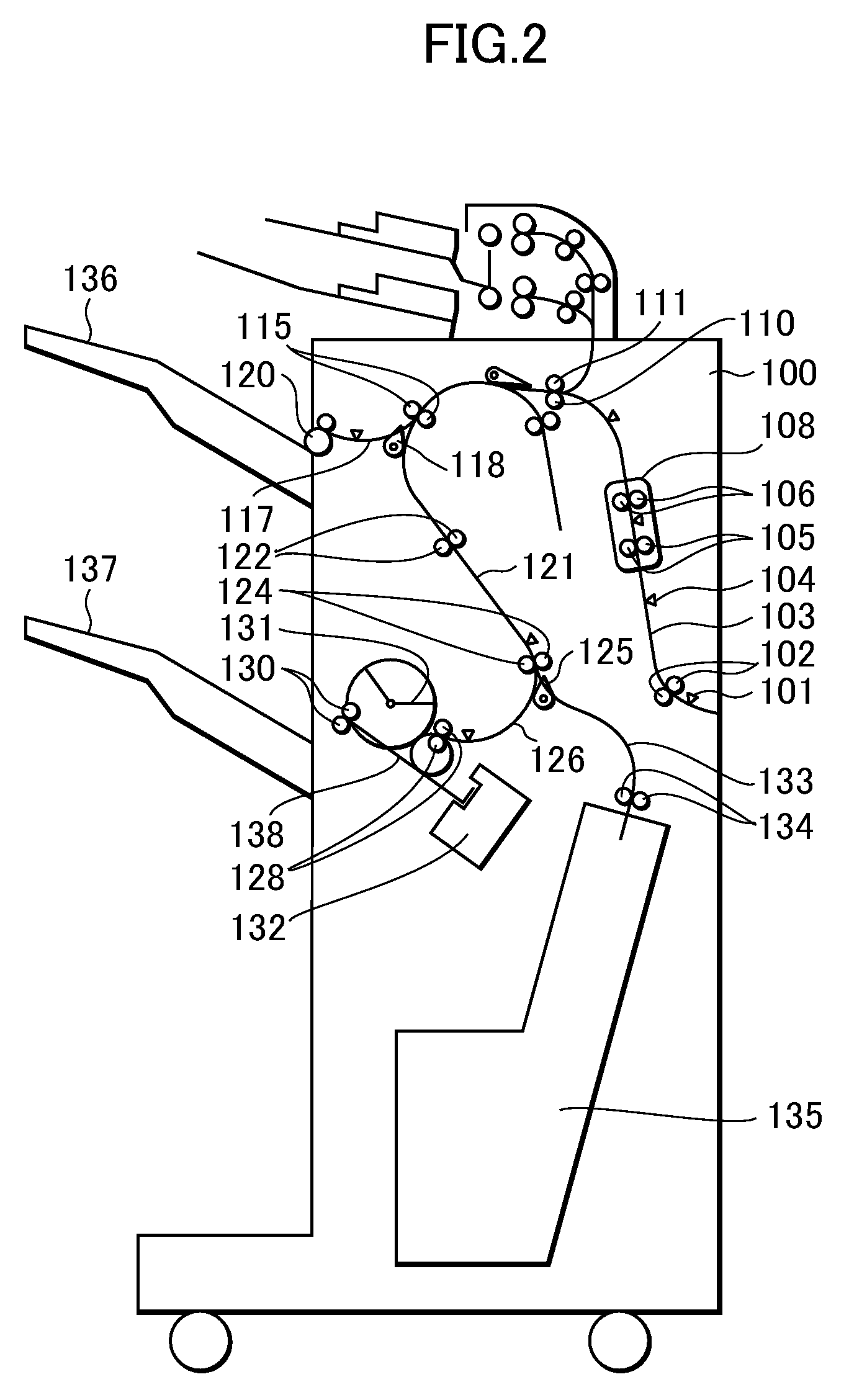
[0032]The image forming system 1 is comprised of a monochromatic / color copying machine body (hereinafter referred to as the copying machine body) 300 and a sheet processing apparatus 100 connected to the copying machine body 300.

[0033]The copying machine body 300 includes an automatic document feeder 500, photosensitive drums 914a to 914d for yellow, magenta, cyan, and black as image forming means, a fixing unit 904, and cassettes 909a to 909d for housing sheets. The copying machine body 300 further includes a control apparatus 950 for controlling the entire copying machine. Sheets are each fed from...


PUM


Abstract

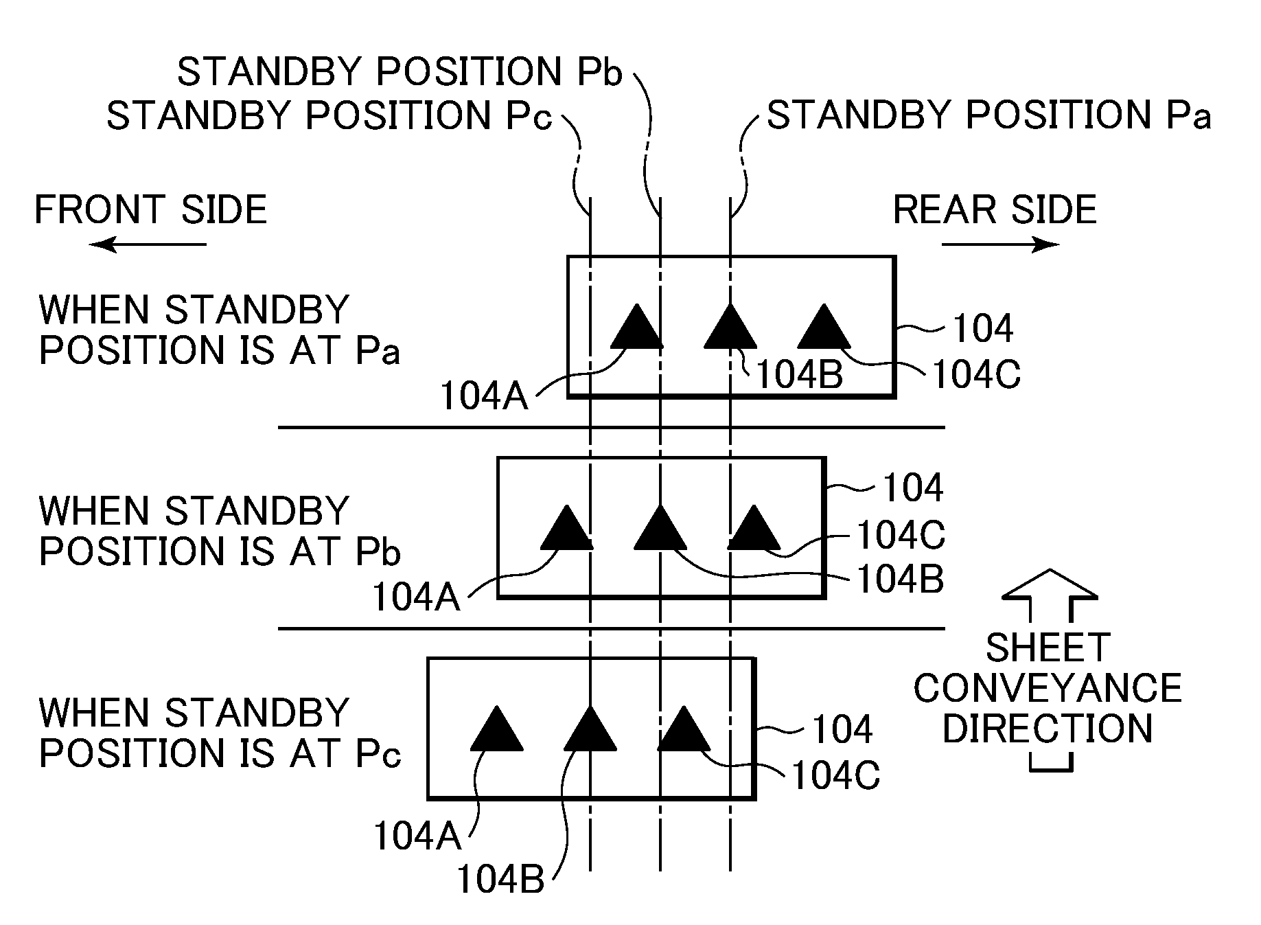
A sheet conveyance apparatus capable of detecting a sheet end portion in a short time period even if sheets are conveyed at a narrow interval and at high speed, thus making it possible to expedite the start timing of a subsequent sheet alignment operation. In accordance with results of detection by lateral registration detection sensors performed when a sheet reaches a lateral registration detection sensor unit, the sensor unit is moved in a width direction for sheet end detection. Based on a moving distance of the sensor unit from a standby position to a position where the sheet end is detected, a shift amount to be shifted the sheet in the width direction, i.e., a lateral registration error, is computed.

Description

BACKGROUND OF THE INVENTION[0001]1. Field of the Invention[0002]The present invention relates to a sheet conveyance apparatus for conveying a sheet on which an image is formed.[0003]2. Description of the Related Art[0004]An image forming apparatus for image formation on a sheet has recently been utilized usually in combination with a sheet processing apparatus, which is called a finisher and connected to the body of the image forming apparatus. The finisher includes a sheet alignment unit for aligning sheets discharged from the image forming apparatus body at their side ends into a bundle, and stales or punches or sorts the bundle of sheets. At the sorting process, some finisher functions to offset sheet bundles in a direction perpendicular to a sheet conveyance direction (hereinafter referred to as the width direction) for distinguishing the sheet bundles from one another, and discharge the sheet bundles.[0005]Since conveyed sheets must be aligned prior to being stapled or punched,...

Claims


Application Information

Patent Timeline
Patent Type & Authority Patents(United States)
IPC IPC(8): B65H7/02
CPCB65H9/106B65H2404/1422B65H2511/20B65H2511/222B65H2553/416B65H2553/81B65H2801/06B65H2220/15B65H2220/03B65H2220/11
Inventor ISHIKAWA, NAOKIFUKATSU, YASUOMORIYAMA, TSUYOSHIKATO, HITOSHI
Owner CANON KK
Learn More