
Small-sized tiller

a small, tiller technology, applied in the direction of travel carriers, golfing accessories, agricultural tools and machines, etc., can solve the problems of inability to keep upright position without tilling units, laborious and time-consuming, and relatively complicated construction of tillers with such kickstands

Active Publication Date: 2011-11-29
HONDA MOTOR CO LTD
View PDF12 Cites 4 Cited by
  • Summary
  • Abstract
  • Description
  • Claims
  • Application Information

AI Technical Summary

Benefits of technology

The present invention provides a small-sized tiller with a resistance-bar attachment hole for stabilizing the posture of the tiller during tilling operation. The stand unit can removably mount the resistance bar and the resistance bar can be easily replaced, cleaned, and maintained. The stand unit has a pole portion that can be engaged with the resistance bar attachment hole for easy attachment. The stand unit has a self-standing structure and a wheel for easy transfer. The stand unit can cover the tilling unit to keep it clean. The small-sized tiller also includes a carrier case for easy handling and a drain hole for draining water from the carrier case. The technical effects of the invention are simplified construction, reduced cost, and improved efficiency of replacement, cleaning, and maintenance of the tilling unit.

Problems solved by technology

However, since the kickstand requires a separate bracket for attachment to the body frame, the tiller having such kickstand becomes relatively complicated in construction and costly to manufacture.
Furthermore, since the tilling unit itself forms a part of the stand unit, the tiller is practically impossible to keep its upright position without the tilling unit.
Accordingly, the known tiller requires a tilling unit (working tool) replacement work which is tedious and time consuming.
The same problem may also occur when the tilling unit is temporarily removed for wishing or maintenance.

Method used


Image

  • Small-sized tiller
  • Small-sized tiller
  • Small-sized tiller

Examples


Embodiment Construction

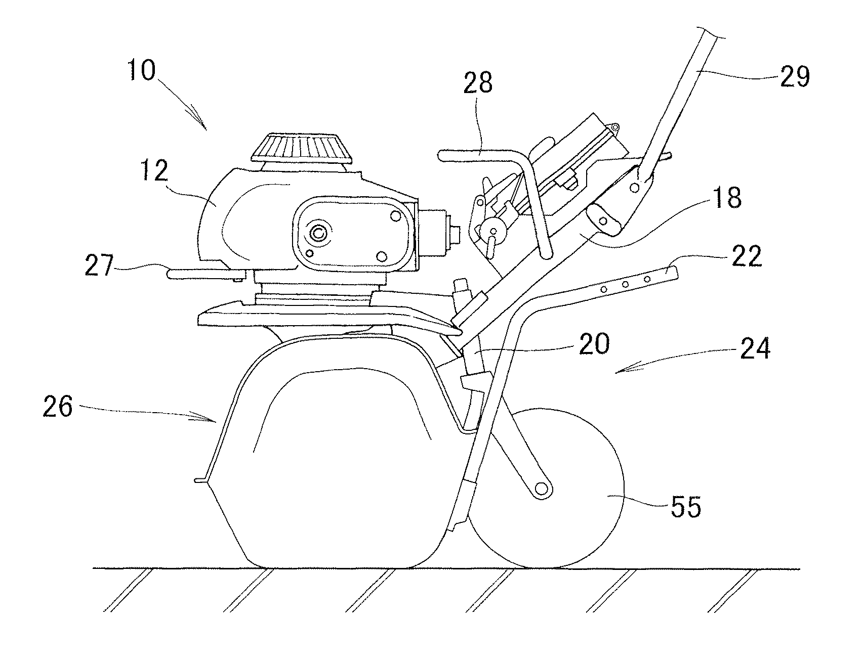
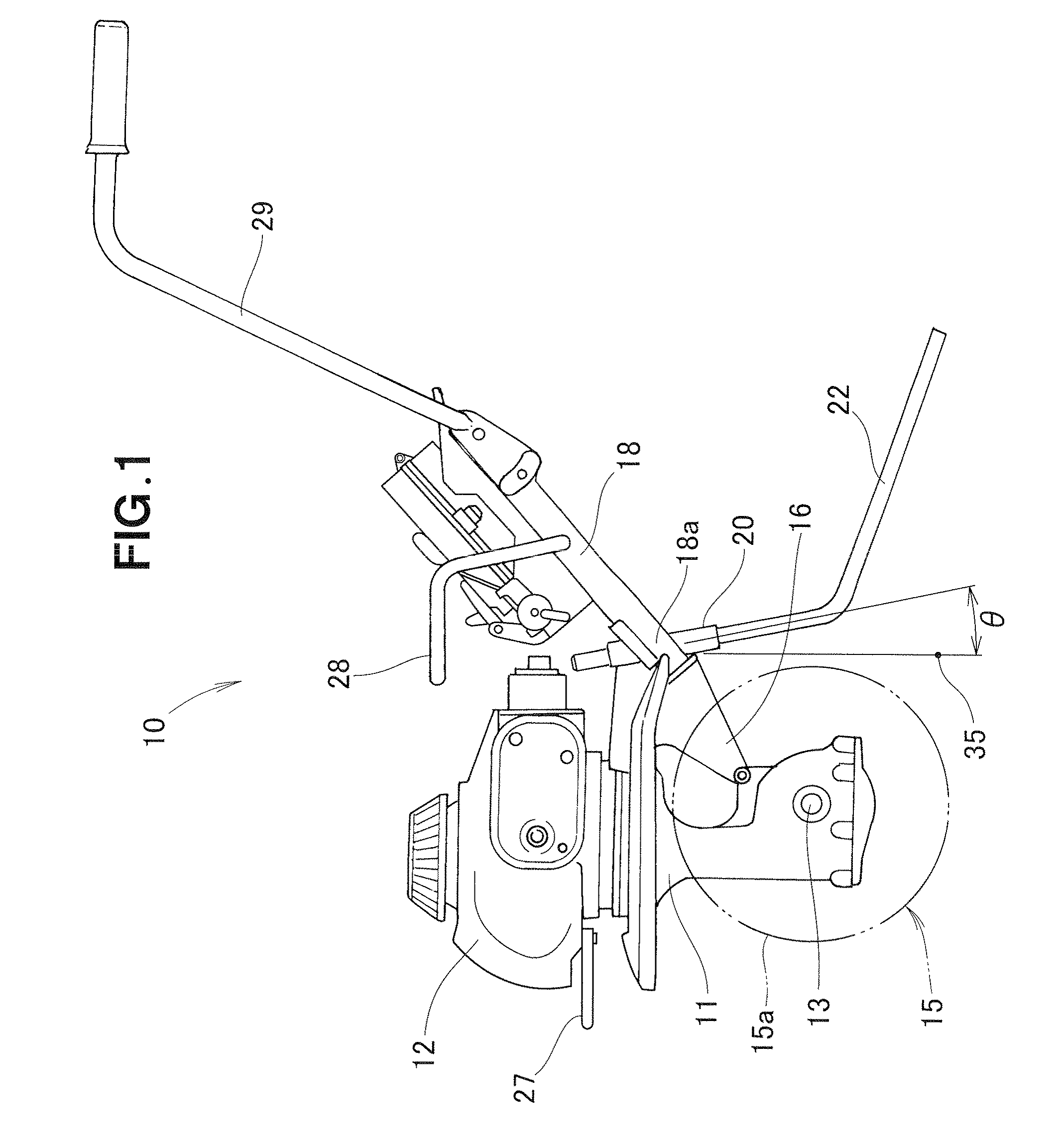
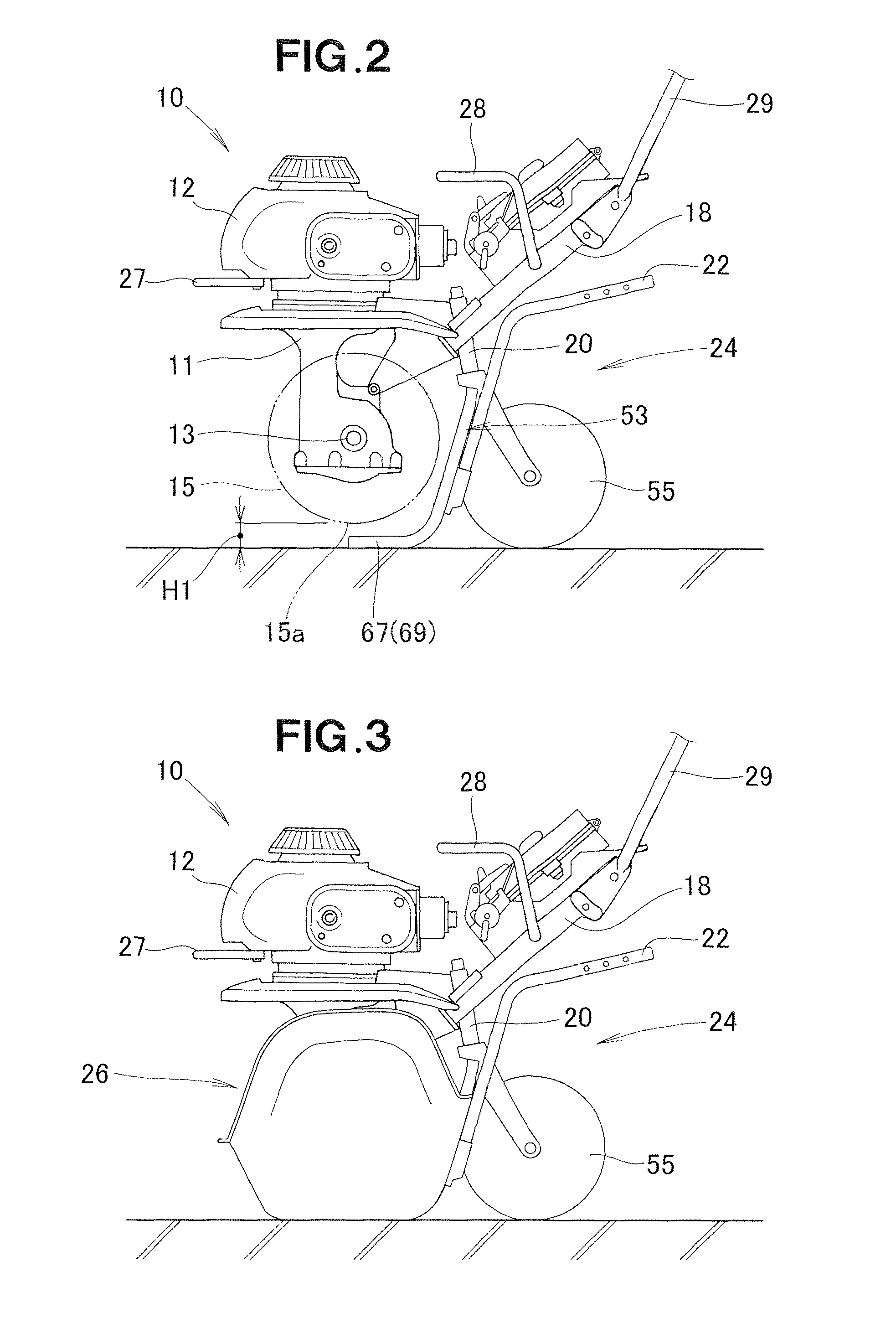
[0030]Referring now to the drawings and FIG. 1 in particular, there is shown a small-sized tiller 10 according to one preferred embodiment of the present invention. The tiller 10 takes the form of a walk-behind tiller and generally comprises a body frame 11, an engine 12 mounted on an upper end of the body frame 11, a horizontal tilling shaft 13 rotatably mounted on a lower portion of the body frame 11, a tilling unit (cultivating tool) 15 removably mounted to the tilling shaft 13 for rotation with the shaft 13 and having a plurality of tilling tines 15a (FIG. 11), a handle column 18 mounted via a bracket 16 to a rear part of the body frame 11 and extending obliquely upward in a rearward direction of the body frame 11, a resistance-bar attachment portion 20 connected to a front end portion of the handle column 18, a resistance bar 22 removably mounted to the resistance-bar attachment portion 20, a carry handle 28 provided on an intermediate portion of the handle column18, and an ope...


PUM


Abstract

A small-sized tiller includes a stand unit configured to solely support the tiller in a self-standing state. The stand unit has a pole portion removably mountable to a resistance-bar attachment portion of the body frame when a resistance bar has been removed from the resistance-bar attachment portion.

Description

CROSS-REFERENCE TO RELATED APPLICATION[0001]This application claims the priority of Japanese Application Nos. P2008-301383, filed Nov. 26, 2008 and P2008-301534, filed Nov. 26, 2008 the entire specifications, claims and drawings of which are incorporated herewith by reference.FIELD OF THE INVENTION[0002]The present invention relates to a small-sized tiller having a resistance bar removably mounted in an attachment hole in the body frame for insertion into the ground to stabilize the posture of the tiller during tilling operation.BACKGROUND OF THE INVENTION[0003]Various small-sized tillers of the type concerned are known and used heretofore. According to one example of such known small-sized tillers, which is disclosed in Japanese Patent Laid-open Publication (JP-A) No. 2006-115777, a kickstand provided at a front portion of the body frame flips down from the body frame and makes contact with the ground to allow the tiller to be kept upright in a condition in which the kickstand, til...

Claims


Application Information

Patent Timeline
Patent Type & Authority Patents(United States)
IPC IPC(8): A01B33/00
CPCA01B33/028A01B33/08A01B33/16A01B76/00
Inventor ITO, TOMOKIAZUMA, KOICHINAKAYA, TOMOMISASAOKA, MASAYUKI
Owner HONDA MOTOR CO LTD
Learn More