
Header over-molded on a feedthrough assembly for an implantable device

a technology of header assembly and feedthrough assembly, which is applied in the field of one-piece header assembly, can solve the problems of increasing device cost and manufacturing cycle time, and the sealing connection between the header assembly and the device is still less reliable than desired, and achieves the effect of improving the sealing of the device, quick and easy manufacturing

Active Publication Date: 2011-11-22
WILSON GREATBATCH LTD
View PDF7 Cites 32 Cited by
  • Summary
  • Abstract
  • Description
  • Claims
  • Application Information

AI Technical Summary

Benefits of technology

The present invention provides a header assembly for an implantable medical device that has improved sealing to the device. The assembly includes a base plate with a surrounding edge and a first feedthrough subassembly. The first feedthrough subassembly has a first ceramic-to-metal seal and first and second feedthrough wires. The assembly also includes a polymeric body molded as a single piece to encase the first and second terminals in a sealed relationship. The invention provides a more secure and better seal of the device, and the assembly is easier and faster to manufacture than previous designs.

Problems solved by technology

These header assemblies require either a backfilled liquid sealing material to be dispensed between the bottom side of the header assembly and the upper lid of the implantable device, or complex mechanical fasteners to firmly secure the header assembly to the device, or both.
These features increase device cost and manufacturing cycle time, while the sealing connection between the header assembly and the device is still less reliable than desired.

Method used


Image

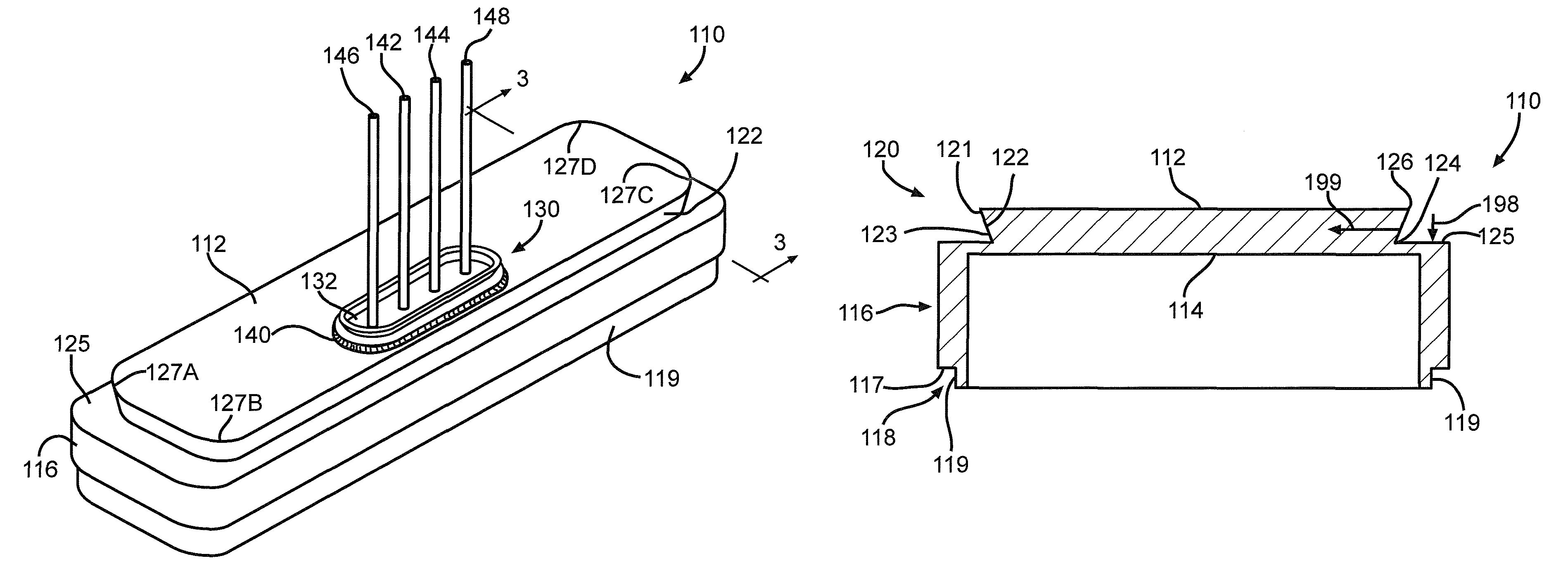
  • Header over-molded on a feedthrough assembly for an implantable device
  • Header over-molded on a feedthrough assembly for an implantable device
  • Header over-molded on a feedthrough assembly for an implantable device

Examples


Embodiment Construction

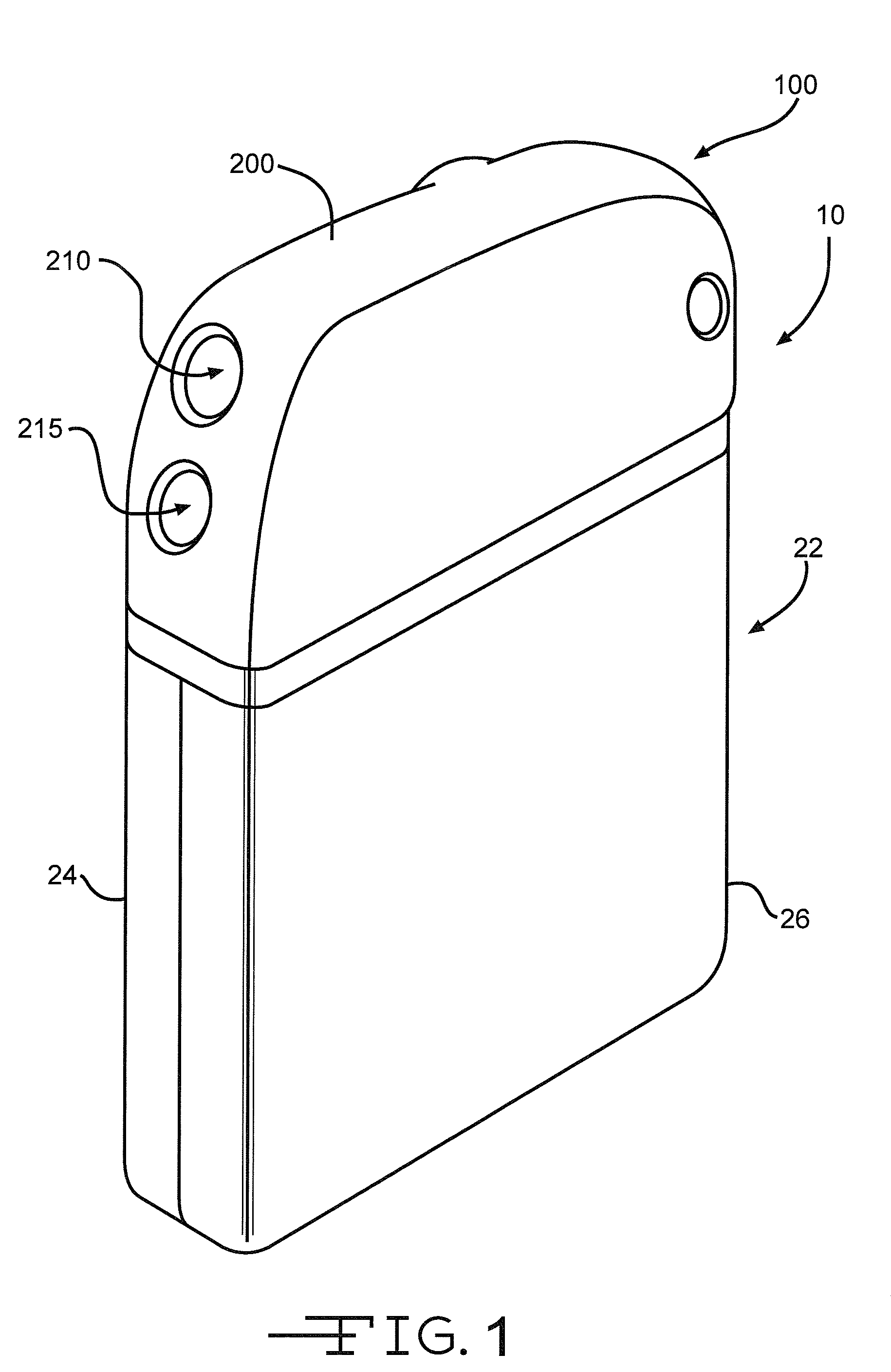
[0044]Turning now to the drawings, FIG. 1 is a perspective view of an implantable medical device 10 including a header assembly 100 of the present invention. FIG. 10 is a similar view of the header assembly 100 with one half of the clamshells comprising the device casing having been removed. The implantable medical device 10 is exemplary of any one of a number of known assist devices such as cardiac defibrillators, cardiac pacemakers, drug pumps, neurostimulators, hearing assist devices, and the like.

[0045]The implantable medical device 10 is contained in a housing 22 of a material such as of stainless steel, and is shown in an exemplary form comprising first and second main clam shell portions 24 and 26. The clam shells 24 and 26 are mated together and hermetically sealed about their periphery to provide an enclosure for the medical device 10. The medical device further comprises control circuitry 12 (FIG. 11) and a power supply 14 such as a battery. The battery is connected to the...


PUM


Abstract

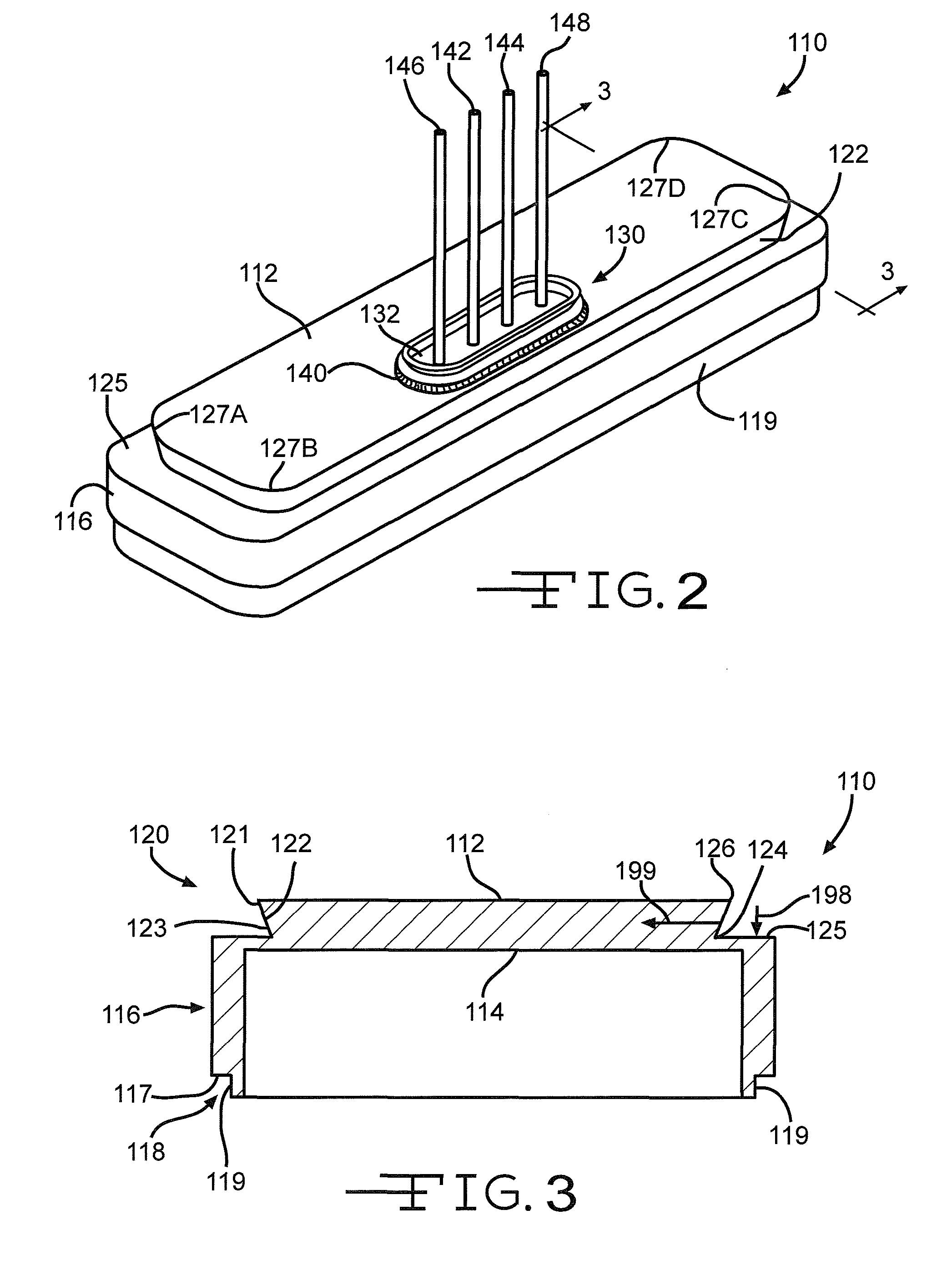
A header assembly for connecting a conductor terminating at a body organ with an implantable medical device is described. The header assembly comprises a base plate, a feedthrough subassembly disposed in the base plate and comprising a ceramic-to-metal seal with first and second feedthrough wires passing through the ceramic-to-metal seal; a first electrically conductive terminal connected to a distal end of the first feedthrough wire and having a first lead opening sized to receive a first portion of a lead for the conductor; a second electrically conductive terminal connected to a distal end of the second feedthrough wire and having a second lead opening sized to receive a second portion of the lead for the conductor; a body of polymeric material molded in a two-part construction to encase the conductive terminals and their feedthrough wires except for a first bore communicating from outside the polymeric body to the first and second lead openings aligned in a first co-axial relationship. Preferably, the polymeric body comprises a first polymeric material such as Techothane® or Polysulfone® encasing the terminals except the bore and an epoxy as a second polymeric material molded over the first polymeric material.

Description

CROSS-REFERENCE TO RELATED APPLICATION[0001]This application claims priority from U.S. provisional Application Ser. No. 61 / 023,624, filed Jan. 25, 2008.BACKGROUND OF THE INVENTION[0002]1. Field of the Invention[0003]The invention relates to a one-piece header assembly for connecting an implantable medical device to a body organ intended to be assisted by the medical device. The header assembly includes a feedthrough assembly that is hermetically welded onto a base plate, which is subsequently welded to the medical device.[0004]2. Description of Related Art[0005]Header assemblies for implantable medical devices generally comprise feedthrough conductors in the form of pins or wires connected to the internal components of the medical device. The feedthrough wires extend through a wall of the medical device housing, such as a lid, and are electrically insulated there from by a ceramic-to-metal seal, and the like. Electrical continuity is established by connecting intermediate conductor ...

Claims


Application Information

Patent Timeline
Patent Type & Authority Patents(United States)
IPC IPC(8): A61N1/375
CPCA61N1/3752A61N1/3754
Inventor BIGGS, JAMES C.
Owner WILSON GREATBATCH LTD
Learn More