
Method and system for simplex or duplex transmission mode of an ethernet link in an energy efficient network

a technology of ethernet link and transmission mode, applied in the field of network, can solve problems such as significant increases in power consumption

Active Publication Date: 2011-11-22
AVAGO TECH INT SALES PTE LTD
View PDF8 Cites 5 Cited by
  • Summary
  • Abstract
  • Description
  • Claims
  • Application Information

AI Technical Summary

Benefits of technology

The patent describes a system and method for transmitting data over an Ethernet network using a simplex or duplex mode. The invention aims to provide an energy-efficient solution for network communication. The technical effects of the invention include improved data transmission efficiency, reduced energy consumption, and improved network performance.

Problems solved by technology

Conventionally, however, increased data rates often result in significant increases in power consumption.

Method used


Image

  • Method and system for simplex or duplex transmission mode of an ethernet link in an energy efficient network
  • Method and system for simplex or duplex transmission mode of an ethernet link in an energy efficient network
  • Method and system for simplex or duplex transmission mode of an ethernet link in an energy efficient network

Examples


Embodiment Construction

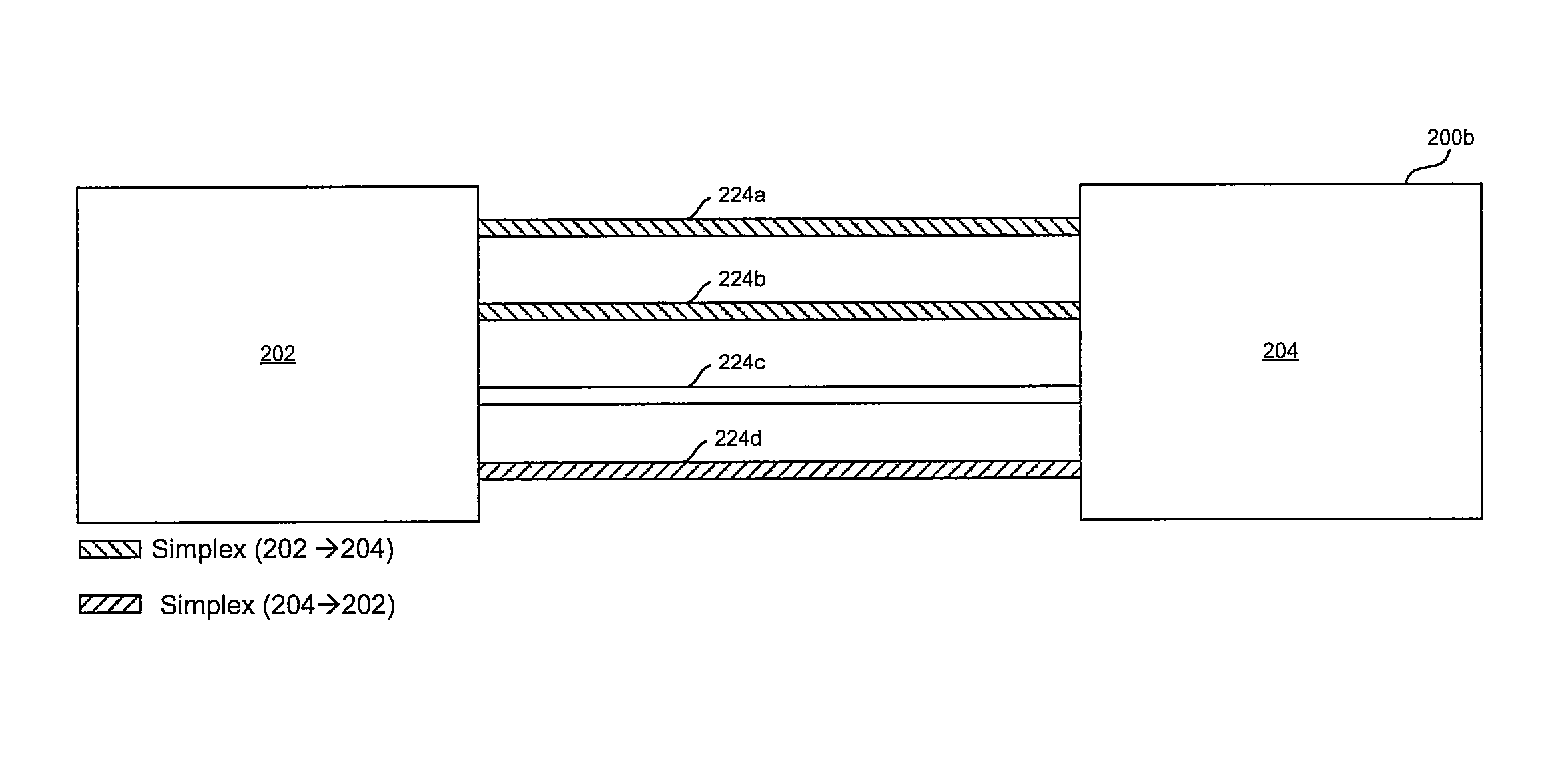
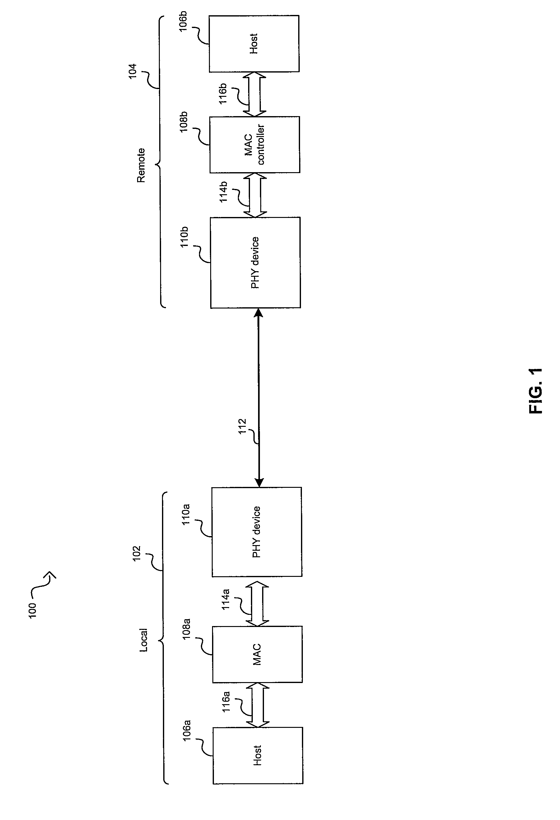
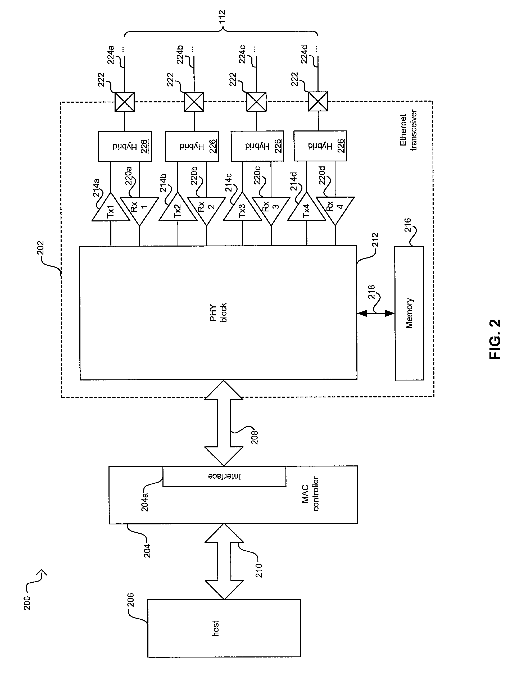
[0022]Certain embodiments of the invention may be found in a method and system for simplex or duplex transmission mode of an Ethernet link in an energy efficient network. An Ethernet network may comprise link partners coupled via an Ethernet link wherein the Ethernet link may comprise one or more channels. The link partners may be configured to operate in simplex mode via the one or more channels based on determined conditions on the Ethernet link during communications via the one or more channels. The determined conditions may comprise, for example, utilization or load on the link partners or Ethernet link, current or past conditions and / or link statistics that may comprise one or more of packet error rate (PER), bit error rate (BER), signal to noise ration (SNR) for example. In addition, one or more of the channels may be transitioned to a lower power mode with a zero data rate. In some embodiments of the invention, one or more of a plurality of operational changes may occur durin...


PUM


Abstract

Ethernet link partners within an Ethernet network, coupled via an Ethernet link comprising one or more channels may be configured to operate in simplex mode based on determined condition(s) during communications via the one or more channels. The determined condition(s) may comprise utilization or load, current / past conditions and / or link statistics that may comprise one or more of packet error rate (PER), bit error rate (BER), and / or signal to noise ratio (SNR). In addition, one or more of the channels may be transitioned to a lower power mode with a zero data rate. In some embodiments of the invention, one or more of a plurality of operational changes may occur during simplex mode operation. For example, power may lowered for one or more components that enable communication such as receivers, transmitters, near-end cross talk cancellers, far-end cross talk cancellers and / or echo cancellers.

Description

CROSS-REFERENCE TO RELATED APPLICATIONS / INCORPORATION BY REFERENCE[0001]This application makes reference to and claims priority to U.S. Provisional Application Ser. No. 61 / 014,183 filed on Dec. 17, 2007, which is hereby incorporated herein by reference in its entirety.[0002]This application makes reference to and claims priority to U.S. Provisional Application Ser. No. 61 / 094,612 filed on Sep. 5, 2008, which is hereby incorporated herein by reference in its entirety.[0003]This patent application also makes reference to:[0004]U.S. patent application Ser. No. 12 / 235,368 which was filed on Sep. 22, 2008;[0005]U.S. patent application Ser. No. 12 / 235,391 which was filed on Sep. 22, 2008;[0006]U.S. patent application Ser. No. 12 / 235,410 which was filed on Sep. 22, 2008; and[0007]U.S. patent application Ser. No. 12 / 235,506 which was filed on Sep. 22, 2008.[0008]Each of the above stated applications is hereby incorporated herein by reference in its entirety.FIELD OF THE INVENTION[0009]Certa...

Claims


Application Information

Patent Timeline
Patent Type & Authority Patents(United States)
IPC IPC(8): H04L12/26
CPCH04L1/0001H04L12/40032H04L12/40039H04L12/413Y02B60/35Y02D30/50
Inventor DIAB, WAEL WILLIAMPOWELL, SCOTT
Owner AVAGO TECH INT SALES PTE LTD
Learn More