Eureka AIR delivers breakthrough ideas for toughest innovation challenges, trusted by R&D personnel around the world.

Dual-feed series microstrip patch array

a patch array and microstrip technology, applied in the field of antennas, can solve the problems of not offering the capability for beam steering for attitude correction, unable to facilitate advanced beam-reconfiguration options, and pointing variation over frequency

Active Publication Date: 2011-11-22
UNIV OF SOUTH FLORIDA
View PDF7 Cites 165 Cited by
  • Summary
  • Abstract
  • Description
  • Claims
  • Application Information

AI Technical Summary

Benefits of technology

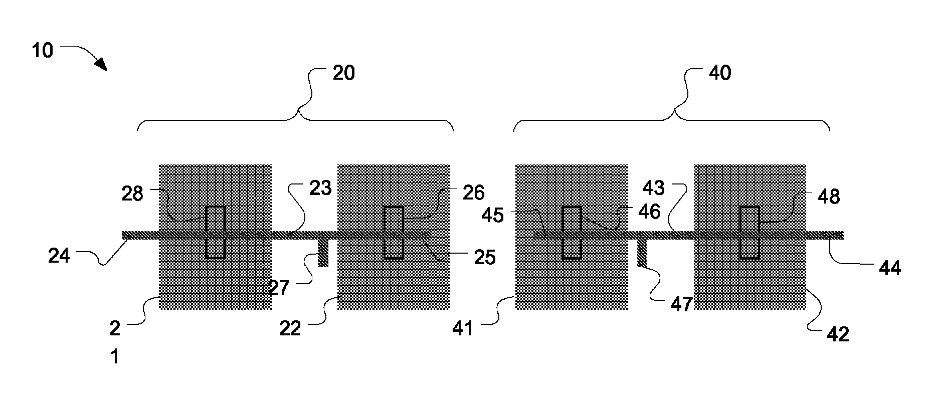
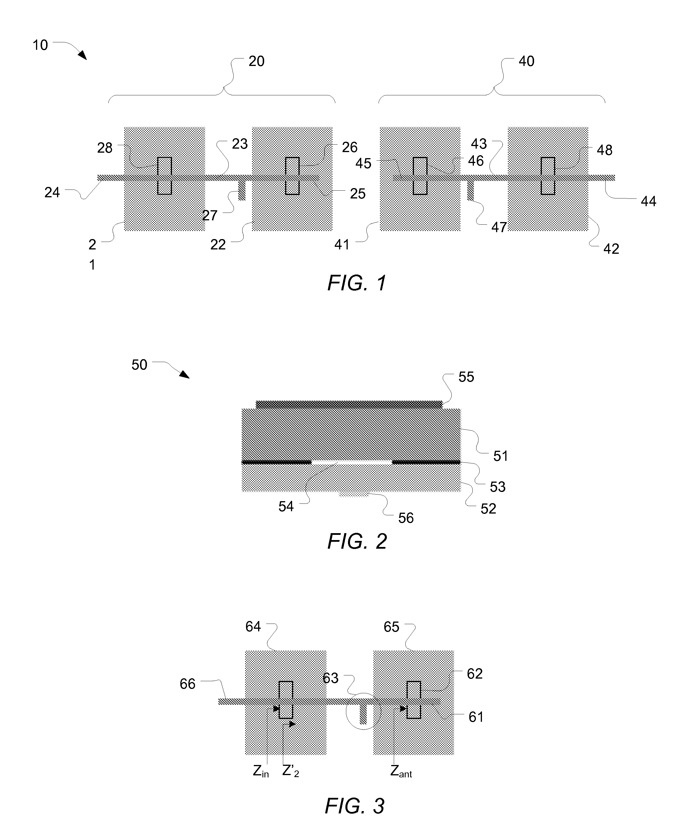
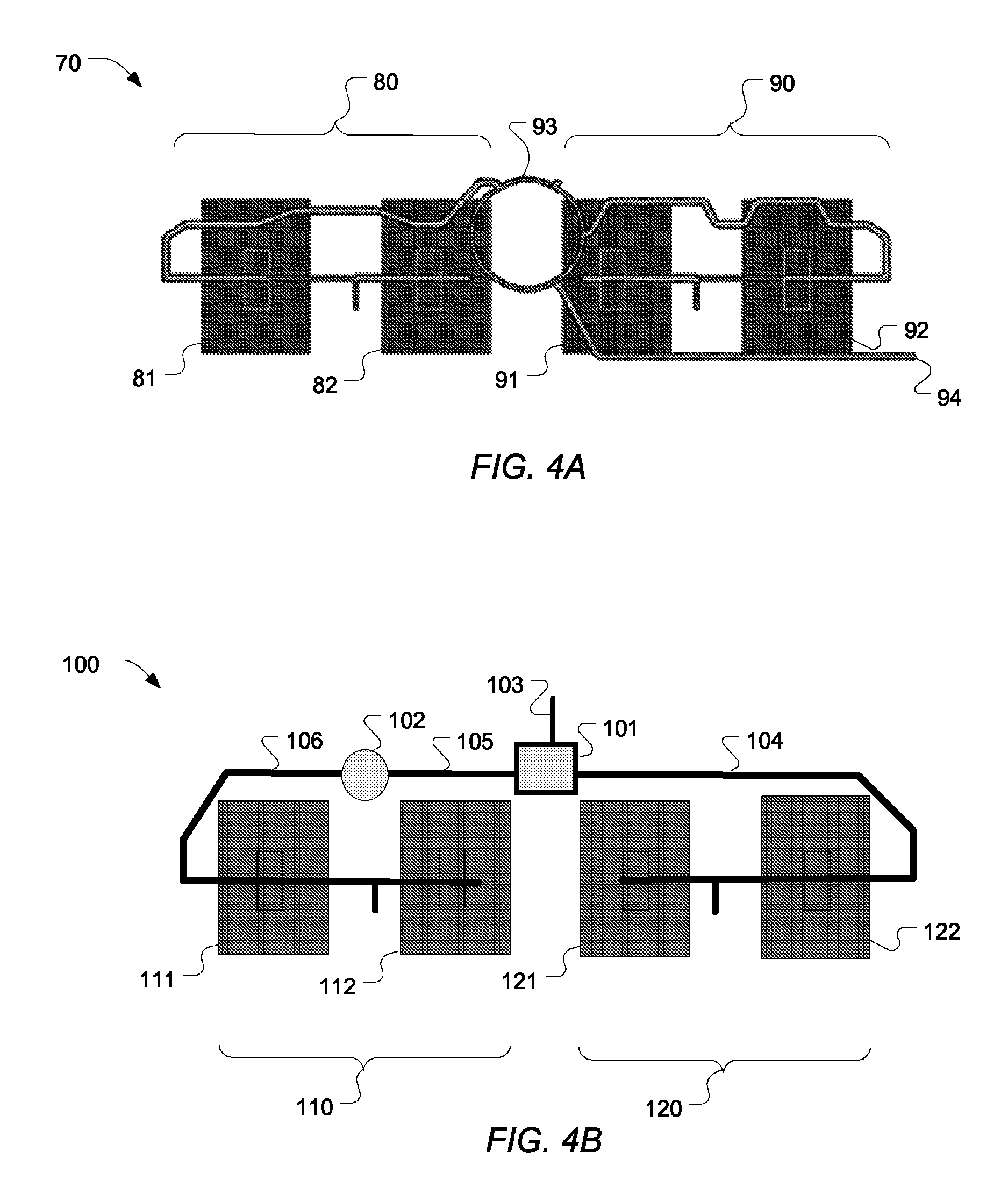
[0005]The present invention includes a dual series-fed, four microstrip patch array antenna that utilizes planar design for ease of fabrication and signal routing. The natural tendency of a series-fed array to have beam tilting over frequency is circumvented by using opposing, anti-symmetric balanced feed...

Problems solved by technology

These approaches typically suffer from beam-pointing variation over frequency, do not offer the capability for beam steering for attitude correction, and do not facilitate advanced beam-reconfiguration options such as eliminating coverage from certain sectors for jamming avoidance.

Method used


Image

  • Dual-feed series microstrip patch array
  • Dual-feed series microstrip patch array
  • Dual-feed series microstrip patch array

Examples


Embodiment Construction

[0039]In the following detailed description of the preferred embodiments, reference is made to the accompanying drawings, which form a part hereof, and within which are shown by way of illustration specific embodiments by which the invention may be practiced. It is to be understood that other embodiments may be utilized and structural changes may be made without departing from the scope of the invention.

[0040]The design of a low-cost microstrip patch antenna suitable for frequency-hopped communications is presented. Two of the main considerations were to achieve an instantaneous bandwidth greater than 10% and to minimize the elevation beam-angle variation over frequency. A suitable solution to these requirements is an N×1 microstrip patch array. As shown herein, the use of an aperture-coupled feed along with the proper choice of substrate materials provides sufficient bandwidth and also avoids the need for live vias or their equivalent. A series-fed approach, combined with an anti-s...


PUM


Abstract

A sub-array of slot-coupled microstrip antennas fed using microstrip lines on an opposing substrate. Also provided is an omni-directional antenna comprised of six of the sub-arrays arranged in a hexagonal fashion. The gain of the antenna is ˜6 dB with a 3 dB elevation beam width of ˜30 degrees. The design provides constant beam angle over frequency, which is important for frequency-hopping applications, and the potential to add beam control to mitigate jamming in different sectors.

Description

CROSS REFERENCE TO RELATED APPLICATIONS[0001]This application claims priority to currently U.S. Provisional Patent Application No. 61 / 044,646 filed Apr. 14, 2008.FIELD OF INVENTION[0002]This invention relates to antennas and more specifically to series-fed aperture-coupled microstrip patch antenna arrays for use in wireless antenna communications.BACKGROUND[0003]Aperture-coupled microstrip patch antennas are desirable structures for use in wireless telecommunications. Their broad use is primarily due to ease of fabrication, low cost, and simplicity of design. These characteristics, combined with the straightforward integration with microstrip distribution networks, make them especially well suited for phased array applications.[0004]High-gain omni-directional antennas find uses in several communications applications including those for small aerial vehicles. Several topologies for omni-directional radiators exist and include linear arrays using bifilar helical elements, periodic rod...

Claims


Application Information

Patent Timeline
IPC IPC(8): H01Q1/38
CPCH01Q9/0457H01Q21/08H01Q21/205
Inventor WELLER, THOMASZIVANOVIC, BOJANA
Owner UNIV OF SOUTH FLORIDA
Why Eureka
Eureka Blog
Learn More