Fluid transporting device using conductive polymer
a technology of conductive polymer and fluid transporting device, which is applied in the direction of positive displacement liquid engine, piston pump, machine/engine, etc., can solve the problems of reducing the operation efficiency of the pump and the diaphragm change, and achieve the effect of improving the work efficiency of the fluid transporting devi
- Summary
- Abstract
- Description
- Claims
- Application Information
AI Technical Summary
Benefits of technology
Problems solved by technology
Method used
Image
Examples
first embodiment
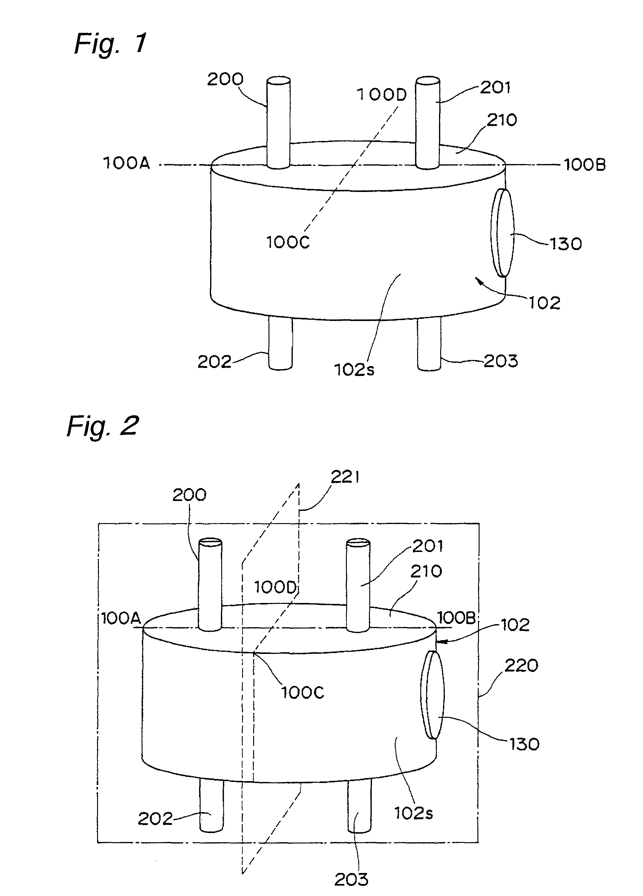
[0099]FIG. 1 is a perspective view that shows a fluid transporting device using a conductive polymer in accordance with a first embodiment of the present invention.
[0100]The fluid transporting device of FIG. 1 is provided with a casing unit 102, an elastic film portion 130 serving as one example of an elastic portion, and respective fluid tube portions 200, 201, 202 and 203.
[0101]The casing unit 102 has a substantially cylindrical shape. Onto the upper and lower round planes 210 of the casing unit 102, the two fluid tube portions 200, 201 and the two fluid tube portions 202, 203 are respectively connected. A round elastic film portion 130 is attached to an opening edge on the outside of a through hole 102h of a side wall 102s of the casing unit 102. For convenience of explanation below, the upper round plane of the casing unit 102 is defined as an upper round plane 210. As shown in FIG. 1, a straight line 100A-100B is a straight line including one diameter of the upper round plane 2...
second embodiment
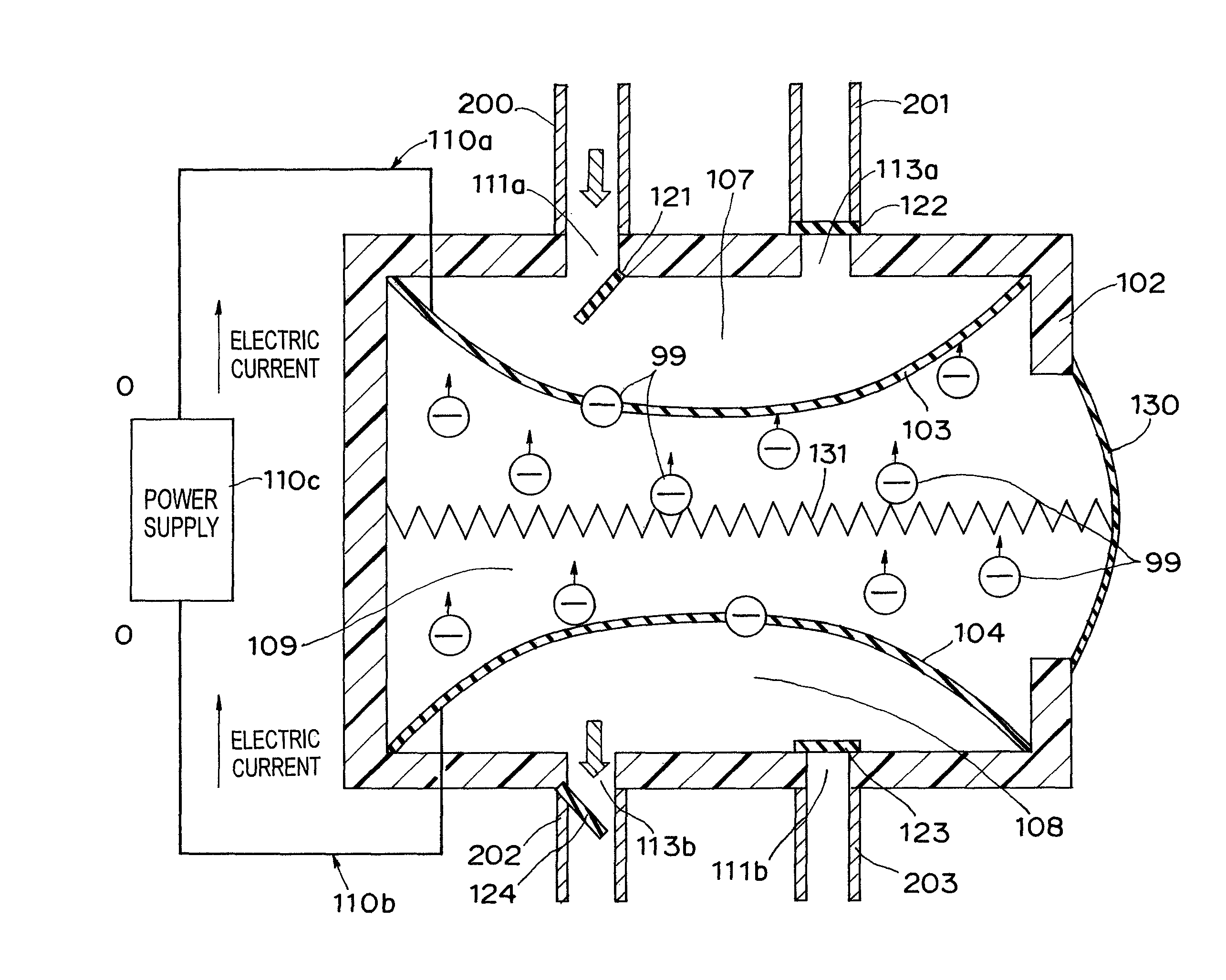
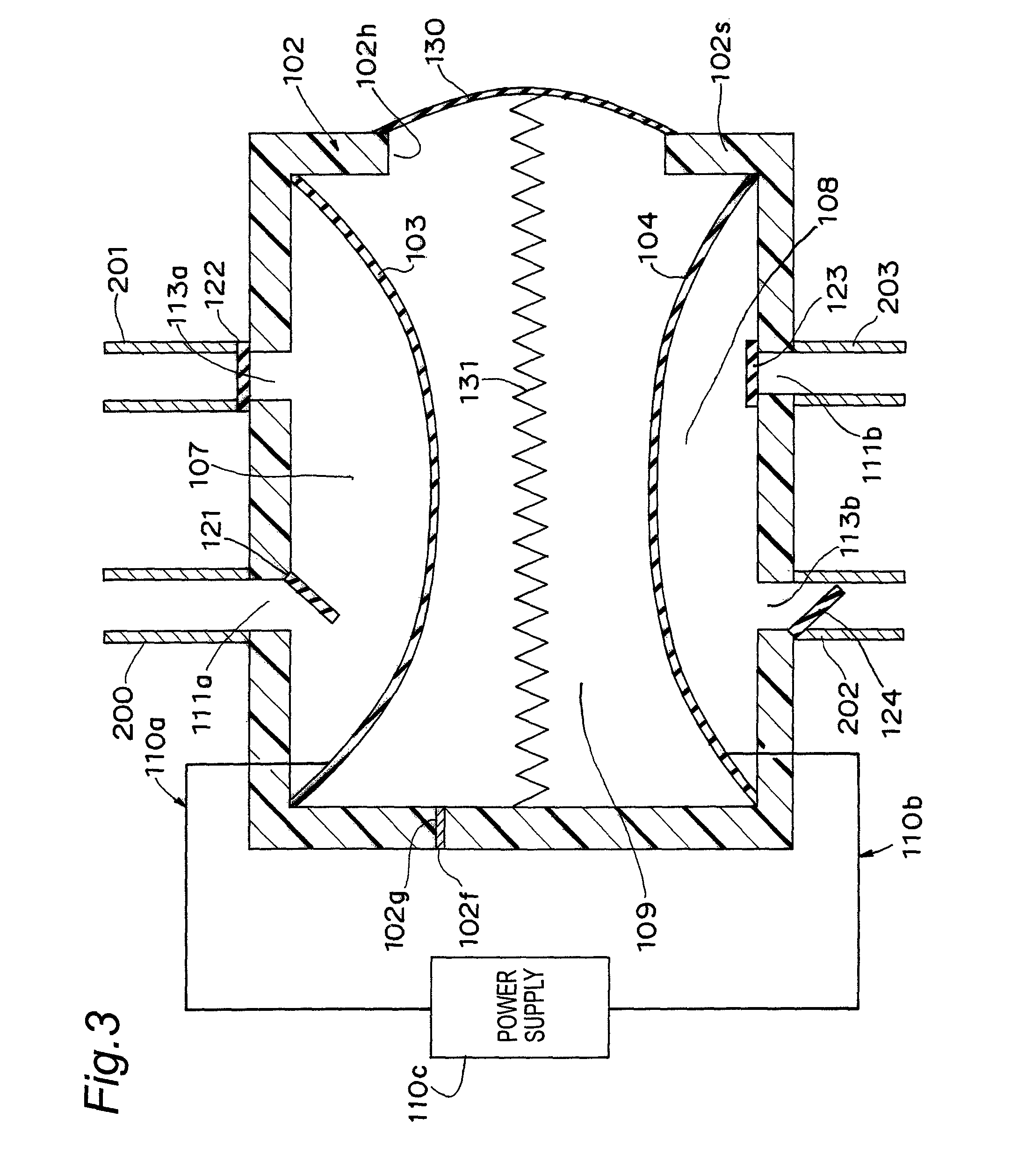
[0178]FIG. 13 is a cross-sectional view that shows a fluid transporting device using a conductive polymer in accordance with a second embodiment of the present invention.
[0179]The fluid transporting device of FIG. 13 is provided with a casing unit 102, a first diaphragm 103, a second diaphragm 104, a first pump chamber 107, a second pump chamber 108, an electrolyte chamber 109, wiring portions 110a and 110b, first and second inlets 111a and 111b, first and second outlets 113a and 113b, first and second inlet valves 121 and 123, first and second outlets 122 and 124, a spring portion 131 and an elastic film portion 130. The spring portion 131 and the elastic film portion 130 serve as a pressure maintaining unit as will be described later. Moreover, for convenience of explanation, the first diaphragm 103 and the second diaphragm 104 are hereinafter referred to simply as diaphragms.
[0180]In the second embodiment, two openings, that is, the first inlet 111a and the first outlet 113a, are...
third embodiment
[0199]FIG. 15 is a cross-sectional view that shows a fluid transporting device using a conductive polymer in accordance with a third embodiment of the present invention.
[0200]The fluid transporting device of the third embodiment is provided with a casing unit 102, a first diaphragm 103, a pump chamber 107, an electrolyte chamber 109, wiring portions 110a and 110b, an inlet 111a, an outlet 113a, an inlet valve 121, an outlet valve 122, a spring portion 131 serving as one example of an elastic portion, an elastic film portion 130, a second elastic film portion 170 and an opposed electrode portion 180. The spring portion 131 and the second elastic film portion 170 serve as a pressure maintaining unit as will be described later.
[0201]The second elastic film portion 170 is secured to the outside edge of the opening of a through hole 102i formed on the bottom face on the lower side of the casing unit 102 so as to air-tightly close the inside of the casing unit 102.
[0202]The two ends of a ...
PUM
 Abstract
Description
Claims
Application Information
 - R&D
- Intellectual Property
- Life Sciences
- Materials
- Tech Scout
- Unparalleled Data Quality
- Higher Quality Content
- 60% Fewer Hallucinations
Browse by: Latest US Patents, China's latest patents, Technical Efficacy Thesaurus, Application Domain, Technology Topic, Popular Technical Reports.
© 2025 PatSnap. All rights reserved.Legal|Privacy policy|Modern Slavery Act Transparency Statement|Sitemap|About US| Contact US: help@patsnap.com


