Method and system for detecting T-wave alternans

a technology of alternans and t-waves, applied in the field of methods and systems for detecting t-wave alternans, can solve problems such as the diagnosis of cardiac electrical instability

Active Publication Date: 2011-11-15
GENERAL ELECTRIC CO
View PDF15 Cites 2 Cited by
  • Summary
  • Abstract
  • Description
  • Claims
  • Application Information

AI Technical Summary

Problems solved by technology

Cardiac electrical instability is diagnosed if the short duration TWA differential measurement exceeds a second high differential limit or if the long duration TWA differential measurement exceeds a low differential limit.

Method used


Image

  • Method and system for detecting T-wave alternans
  • Method and system for detecting T-wave alternans
  • Method and system for detecting T-wave alternans

Examples


Embodiment Construction

[0016]In the following detailed description, reference is made to the accompanying drawings that form a part hereof, and in which is shown by way of illustration specific embodiments that may be practiced. These embodiments are described in sufficient detail to enable those skilled in the art to practice the embodiments, and it is to be understood that other embodiments may be utilized and that logical, mechanical, electrical and other changes may be made without departing from the scope of the embodiments. The following detailed description is, therefore, not to be taken as limiting the scope of the invention.

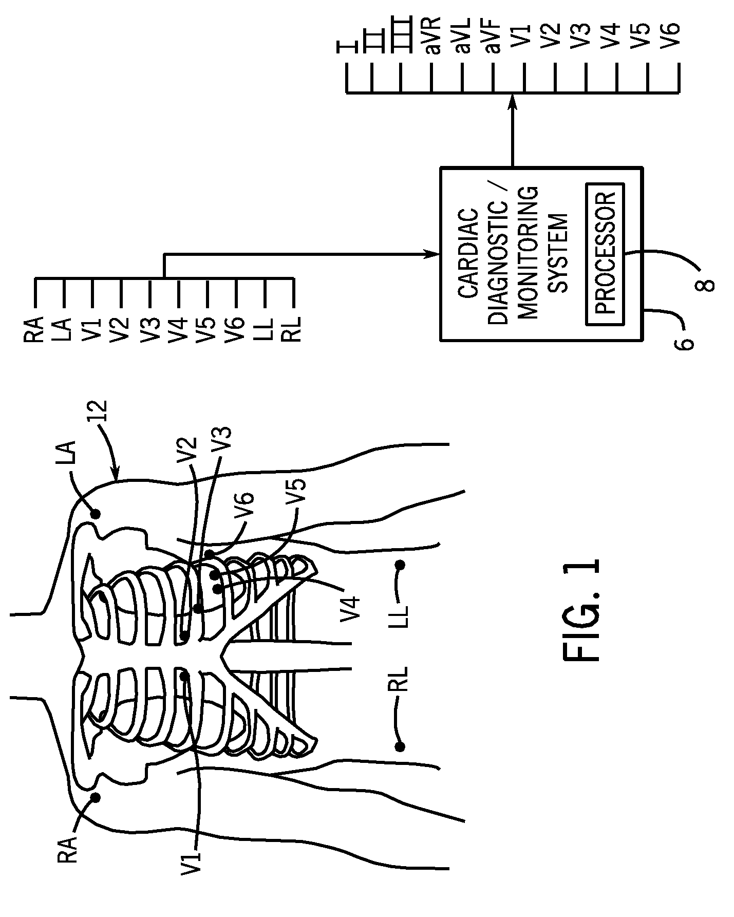
[0017]Referring to FIG. 1, a schematically represented cardiac diagnostic / monitoring system 6 is adapted measure an electrical signal generated by a patient's heart. The cardiac diagnostic / monitoring system 6 can be coupled to the patient 12 by an array of sensors or transducers. In the illustrated embodiment, the array of sensors include a right arm electrode RA; a left arm e...


PUM


Abstract

A method for generating a cardiac electrical instability assessment is disclosed herein. The method includes obtaining a short duration T-wave alternans (SDTWA) measurement, obtaining a long duration T-wave alternans (LDTWA) measurement, and obtaining a cardiac electrical instability assessment based on both the SDTWA measurement and the LDTWA measurement.

Description

BACKGROUND OF THE INVENTION[0001]This disclosure relates to method and system for detecting T-wave alternans.[0002]An electrocardiogram (ECG) of a single heartbeat is commonly referred to as a PQRST complex. The PQRST complex includes a P-wave that corresponds to activity in the atria, a QRS complex that represents the electrical activation of the ventricles, and a T-wave that represents the electrical recovery or recharge phase of the ventricles. The PQRST complex also includes an ST segment connecting the QRS complex and the T-wave. T-wave alternans (TWA) is an electrophysiological phenomenon that is evident in the ECG as an alternating pattern of ST segment and / or T-wave morphologies on successive beats.[0003]Clinical studies have demonstrated that TWA is an indicator of cardiac electrical instability. One problem is that it is difficult to identify and measure the specific TWA morphological patterns that are most indicative of cardiac electrical instability.SUMMARY OF THE INVENT...

Claims


Application Information

Patent Timeline
Patent Type & Authority Patents(United States)
IPC IPC(8): A61B5/0402
CPCA61B5/0452A61B5/349
Inventor ROWLANDSON, GORDON IANKAISER, WILLISLAWNYCH, MICHAELXUE, JOEL QIUZHENEXNER, DEREK
Owner GENERAL ELECTRIC CO
Why Eureka
Try Eureka