
Biconical antenna assembly

a biconical antenna and antenna technology, applied in the field of biconical antenna assemblies, can solve the problems of short-range wireless devices posing a significant risk to combatants, unintended use in supporting military or terrorist activities of non-friendly countries, and a risk of detection or injury from the ied itsel

Active Publication Date: 2011-11-15
SIERRA NEVADA CORP
View PDF5 Cites 10 Cited by
  • Summary
  • Abstract
  • Description
  • Claims
  • Application Information

AI Technical Summary

Benefits of technology

[0011]Embodiments of the invention include a transceiver that suppresses one or more signals transmitted from a target transmitter in an RF transmission system to a target receiver in a wireless device operating in the RF transmission system to detect, prevent, disrupt, jam, interfere with or otherwise disable an RF transmission between the target transmitter and the target receiver in the wireless device (i.e., target wireless device).

Problems solved by technology

While commercial RF transmission systems are generally thought to improve the overall well-being of mankind and to advance our society, they have found an unintended use in supporting military or terrorist activity of non-friendly countries, organizations, factions, combatants or other groups.
While many commercial RF transmission systems are not secure, their cost and widespread availability, make them an attractive alternative.
Accordingly, these short range wireless devices pose a significant risk to a combatant (e.g. a terrorist, a foe, a member of a non-friendly group or organization, a neutral party, or other combatant) either in the form of risk of detection or risk of injury from the IED itself.
Existing antennae such as conventional dipoles and monopoles suffer from a number of limitations, including narrow frequency coverage, heavy weight, and high visual profile.
The discone antenna is capable of operation over frequency bandwidths of 10-15:1, however, the beam peak varies considerably from the horizon with frequency, thus affecting useful range.
Biconical dipoles that are symmetrical are well known, but provide limited capability, e.g., provide bandwidths comparable to “fat” dipoles.

Method used


Image

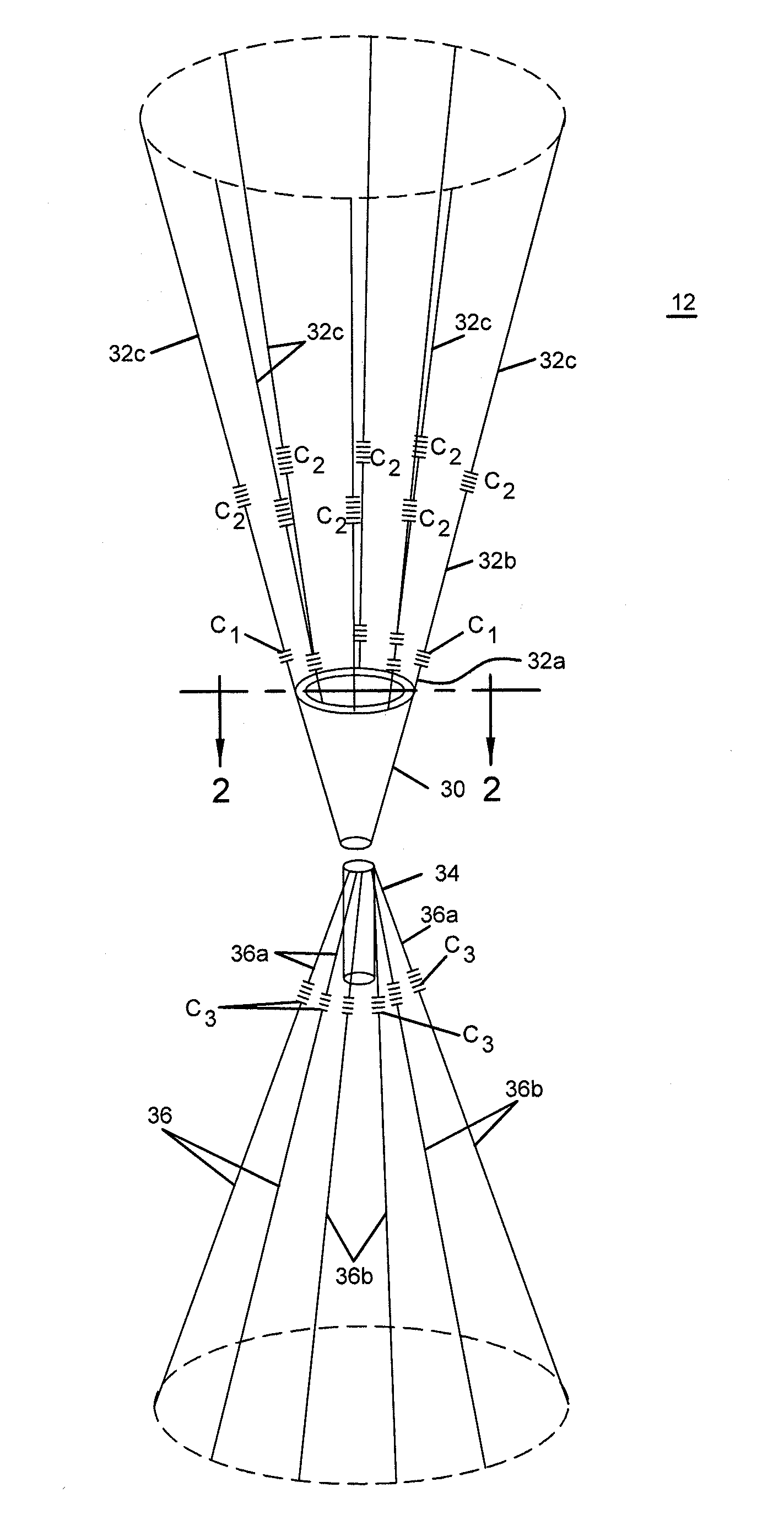
  • Biconical antenna assembly
  • Biconical antenna assembly
  • Biconical antenna assembly

Examples


Embodiment Construction

[0022]Referring briefly to FIG. 8, which shows a radiofrequency system including portable antenna 12 and a remote transceiver 14 operates as a base station and relaying an RF signal to a target wireless receiving device 16, for example an improvised explosive device (“IED”). Portable antenna 12 can be used with a transceiver in a defensive manner to detect or suppress RF transmissions from remote transceiver 14 and / or target receiving device 16.

[0023]In some environments, if the target transceiver 14 is unable to initiate or otherwise establish and / or maintain an RF transmission with the target wireless receiving device 16, the target wireless device may not be used for communication, command and control. In other applications, if the target transceiver 14 is unable to initiate or otherwise establish and / or maintain an RF transmission with the target wireless device 16, the target wireless device may not be used as, or as part of, a detonator for an IED. Various other embodiments of...


PUM


Abstract

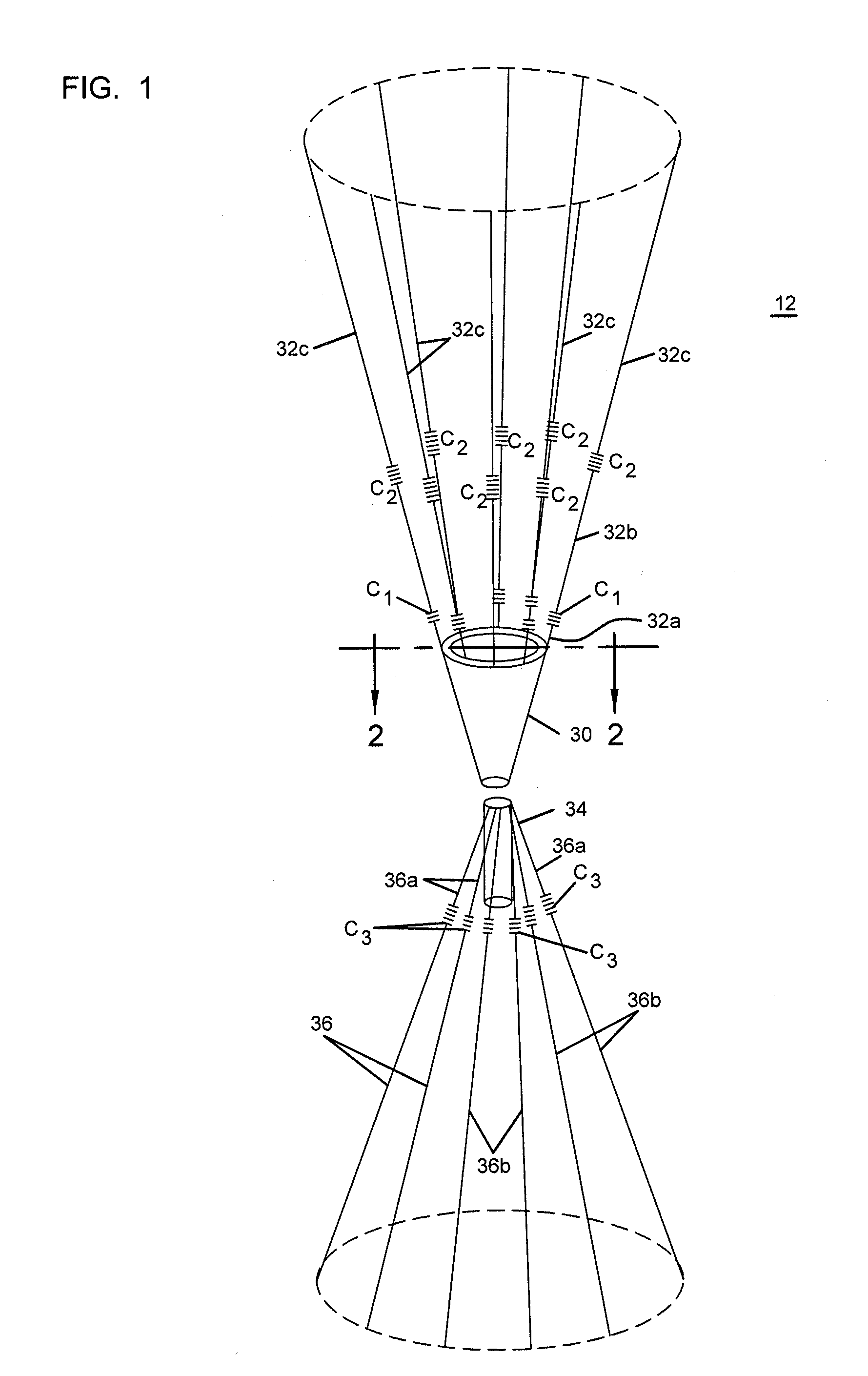
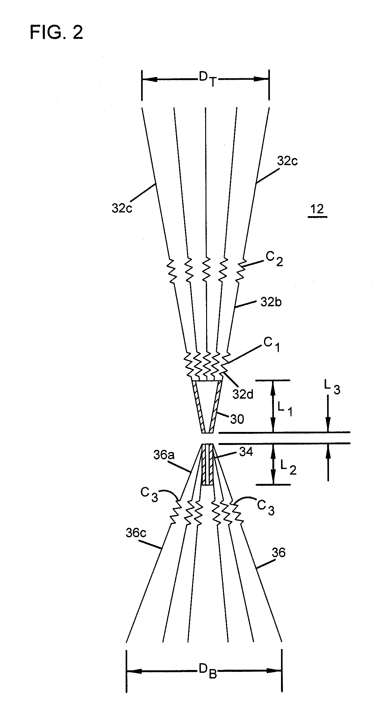
An biconical antenna assembly including a pair of conductors each having a plurality of radiating conductors. One of the conductors defines a cone shape and radiating conductors extending to define a generally conical form. The other conductor defines a cylindrical shape and radiating conductors extend to define another generally conical form. The conical forms are defined by a pair of sheet conductors and radiating conductors generally divergent about a center point or axis. A feed point is defined generally at the center point. Multiple RF chokes can be provided on the radiating conductors to optimize performance of the antenna over a predetermined frequency range.

Description

RELATED APPLICATIONS[0001]This application claims the benefit of priority of U.S. Ser. No. 61 / 012,649, filed Dec. 10, 2007, which is hereby incorporated by reference in its entirety.TECHNICAL FIELD[0002]The invention relates generally to antennas for operation over multiple frequency bands and more particularly to electronic systems intended to detect or suppress (e.g., prevent, disrupt, jam, interfere with or otherwise disable) radio frequency transmissions between transmitters and receivers occurring within particular frequency bands.BACKGROUND OF THE INVENTION[0003]Radio frequency (“RF”) transmission systems and the various wireless devices that operate within such systems are commercially widely available, and nearly ubiquitous, throughout the world with systems coming on-line daily even in the remotest areas of the world. While commercial RF transmission systems are generally thought to improve the overall well-being of mankind and to advance our society, they have found an uni...

Claims


Application Information

Patent Timeline
Patent Type & Authority Patents(United States)
IPC IPC(8): H01Q13/00
CPCH01Q1/20H01Q1/3283H01Q9/28H04K3/40H01Q5/321H01Q5/25H04K3/92H04K2203/16H04K2203/24H04K2203/32H04K3/42
Inventor JOHNSON, GREG
Owner SIERRA NEVADA CORP
Learn More