Eureka AIR delivers breakthrough ideas for toughest innovation challenges, trusted by R&D personnel around the world.

Surgical obturator

Inactive Publication Date: 2011-11-15
AESCULAP AG
View PDF32 Cites 23 Cited by
  • Summary
  • Abstract
  • Description
  • Claims
  • Application Information

AI Technical Summary

Benefits of technology

The object of the invention is to design a surgical obturator of the above general type in such a way that the risk of an injury to internal organs during piercing of a body wall is reduced.
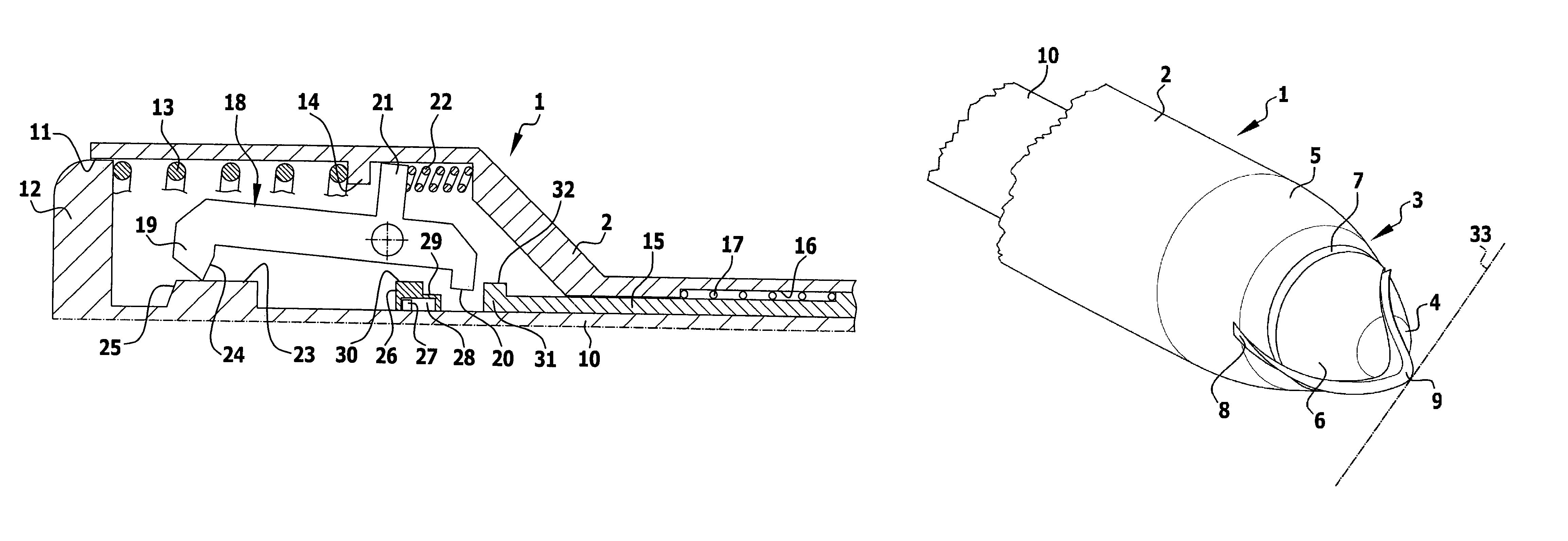
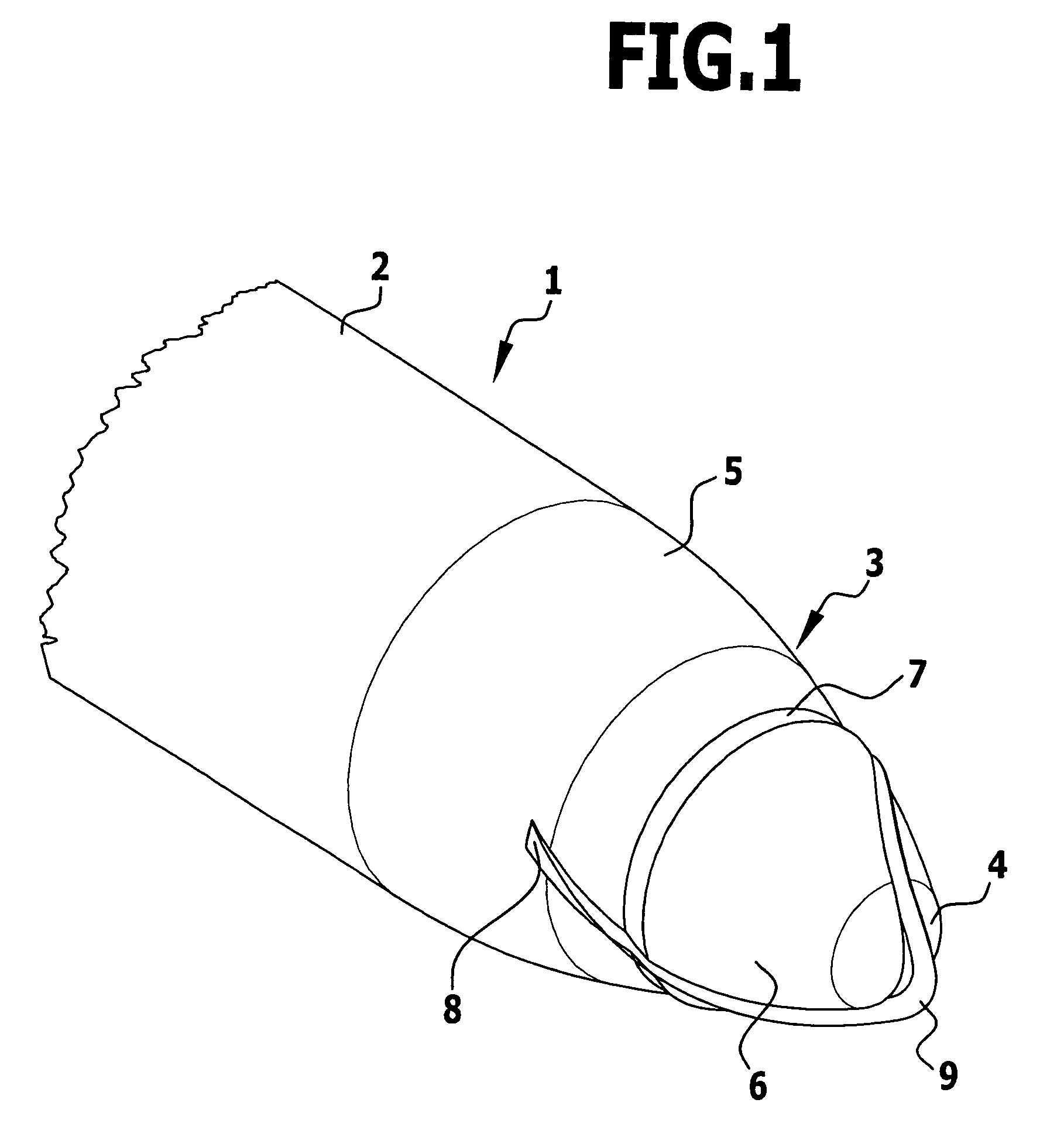
The shape of the blade may differ widely, being for example V-shaped, a blade having a helical-line-shaped cutting edge being particularly advantageous. Such a helical-line-shaped cutting edge facilitates the delicate insertion of the obturator into a body wall and also results in the blade during retraction being moved, by virtue of the guidance of the blade in a guide slot of the protective cap, helically and hence in accordance with the piercing motion that the surgeon carries out likewise in a helical-line-shaped manner.

Problems solved by technology

When the obturator is being advanced, there is a risk that the obturator, once it has passed right through the body wall, may be advanced further in an uncontrolled manner and the blade disposed on the front end of the obturator may cause injury to internal organs.
Advancing the protective shield can likewise lead to injuries, as it often shoots forward abruptly under the action of a spring, and it is moreover usually necessary for the obturator to have fully penetrated the body wall before activation of the protective shield may occur.

Method used


Image

  • Surgical obturator
  • Surgical obturator
  • Surgical obturator

Examples


Embodiment Construction

The obturator 1 represented in the drawings comprises a tubular housing 2, of which in FIGS. 1, 11, 13 and 15 in each case only the front part is shown. The housing 2 terminates in this front part with a truncated-cone-shaped introduction tip 3, the tip 4 of which is rounded. The introduction tip 3 is subdivided into two portions, namely a proximal portion 5, which is part of the housing 2, and a central protective cap 6, which is displaceable relative to the housing and hence relative to the proximal portion 5 in axial direction between two end positions, namely a retracted (proximal) working position and an advanced (distal) inoperative position. In the retracted working position the outer surface of the protective cap 6 merges continuously into the outer surface of the proximal portion 5 (FIG. 13), in the advanced inoperative position a step 7 is formed between the protective cap 6 and the proximal portion 5 of the introduction tip 3 (FIG. 1).

Running through its tip 4 the protect...


PUM


Abstract

In a surgical obturator for piercing a body wall, comprising a tubular housing that at one end forms an introduction tip with a continuously decreasing diameter, and comprising a blade projecting from the introduction tip for making an incision in the body wall, in order to reduce the risk of injury during piercing of the body wall it is proposed that the introduction tip comprises a central protective cap, which is displaceable in longitudinal direction relative to the introduction tip between an advanced inoperative position and a retracted working position, that the blade in the housing is displaceable in longitudinal direction between an advanced cutting position and a retracted protected position, that disposed in the housing is a retraction device that displaces the blade from the cutting position into the protected position, and that the retraction device may be activated by a displacement of the protective cap from the working position into the inoperative position.

Description

This application is a continuation of International patent application no. PCT / EP2007 / 003881 filed on May 3, 2007 and claims the benefit of German patent application no. 10 2006 024 757.4 filed May 27, 2006, each of which is incorporated herein and made a part hereof by reference.BACKGROUND OF THE INVENTIONThe invention relates to a surgical obturator for piercing a body wall, comprising a tubular housing that at one end forms an introduction tip with a continuously decreasing diameter, and comprising a blade projecting from the introduction tip for making an incision in the body wall.Such obturators are used to form openings in a body wall for a cannula or a tube, which tube may be for example a trocar tube, through which instruments are introduced into the body.When the obturator is being advanced, there is a risk that the obturator, once it has passed right through the body wall, may be advanced further in an uncontrolled manner and the blade disposed on the front end of the obtu...

Claims


Application Information

Patent Timeline
IPC IPC(8): A61B17/34
CPCA61B17/3496A61B17/3474
Inventor MALIGLOWKA, JOHANNMAYENBERGER, RUPERTSCHWEITZER, TOM
Owner AESCULAP AG
Why Eureka
Eureka Blog
Learn More