
Local edge count heuristic for vector interpolator

Active Publication Date: 2011-11-08
SYNAPTICS INC +1
View PDF19 Cites 5 Cited by
  • Summary
  • Abstract
  • Description
  • Claims
  • Application Information

AI Technical Summary

Benefits of technology

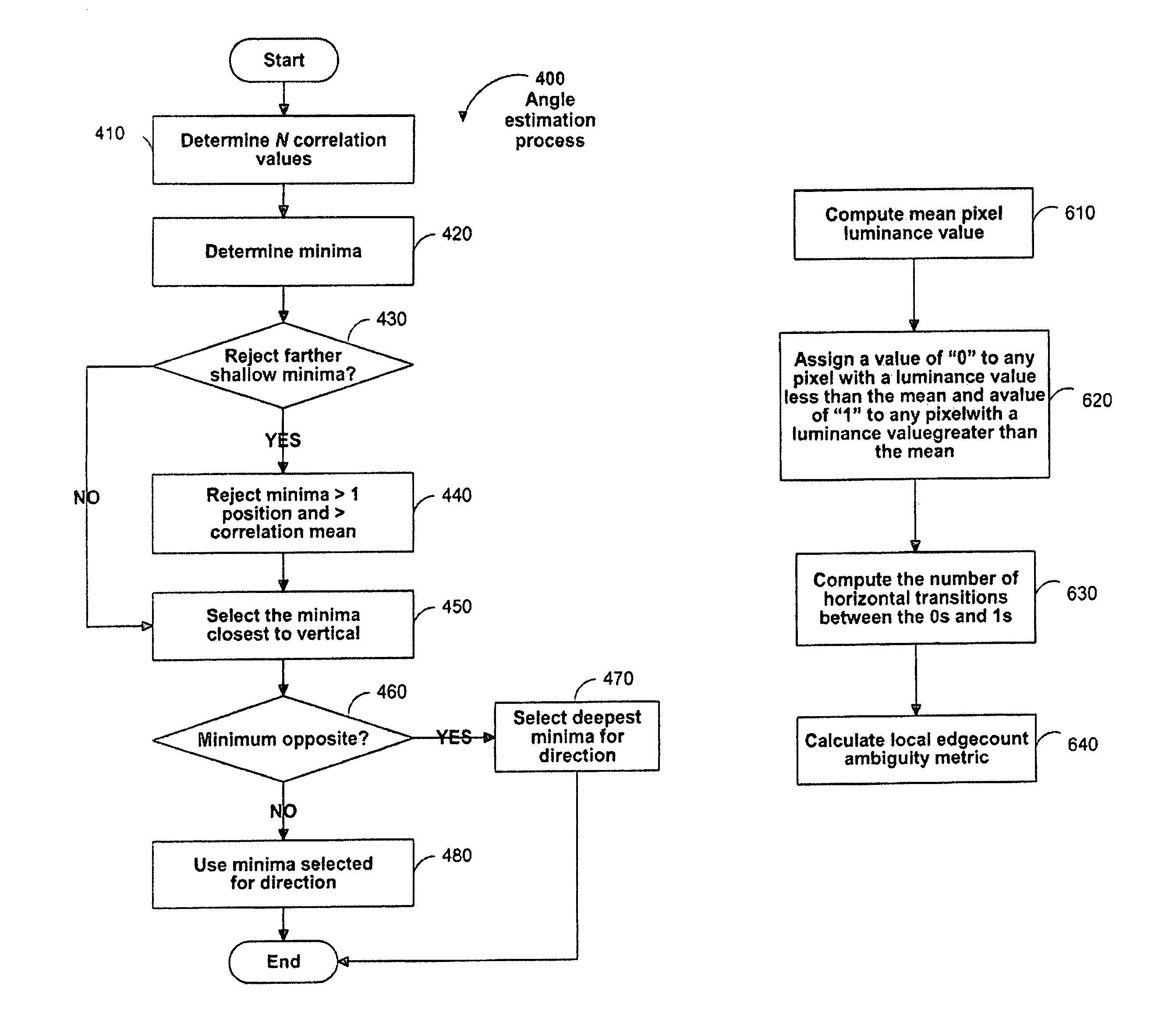
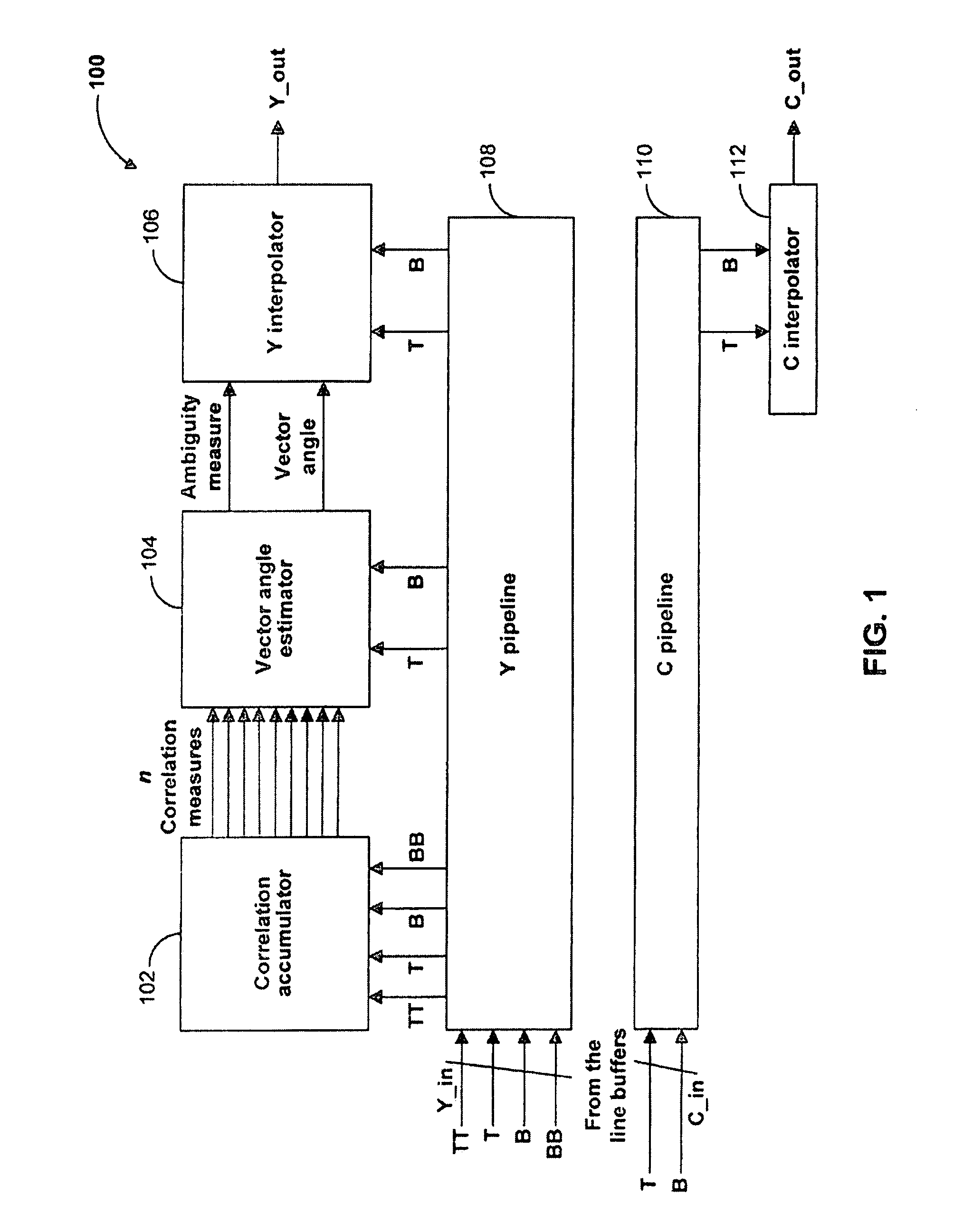
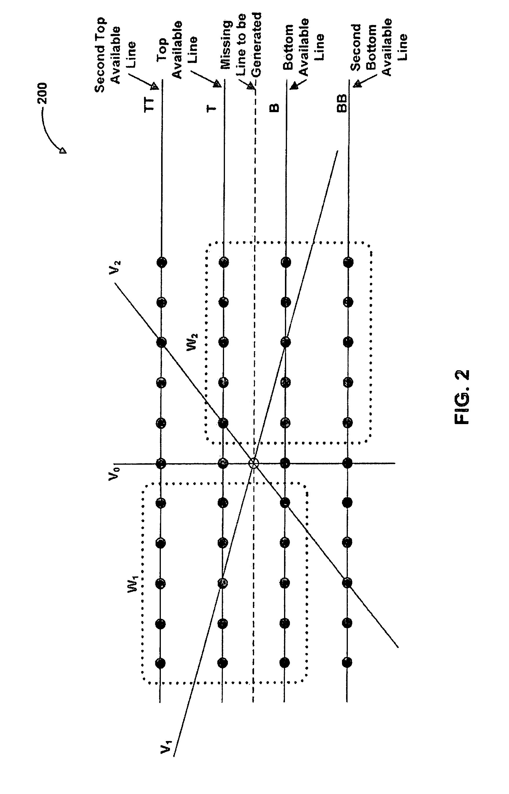
[0005]Briefly stated, a vector interpolator optimizes the conversion of an interlaced signal to a non-interlaced signal. The vector interpolator improves the visual clarity of slanted features in a displayed image by adjusting the luminance value of each pixel such that the appearance of “steps” or “jaggies” in the features is reduced. For each pixel, the vector interpolator determines a similarity measure for the pixels within a predetermined area around the pixel. From the similarity measure, an angle for interpolation is selected. The luminance value is then interpolated along the selected vector corresponding to the angle and applied to the pixel.
[0006]When a video display is de-interlaced, the scan line visibility is reduced due to the doubling the number of lines. The vector interpolator described herein improves the line-doubling process by interpolating the luminance values for the pixel from the surrounding pixels. As stated, by interpolating along a selected angle from the pixel to be generated, a more accurate luminance value is applied to the pixel. This method contrasts with doubling of lines by vertical interpolation, where the values applied to a newly generated pixel are interpolated from the pixels directly above and below the position for the new pixel. Doubling the lines by vertical interpolation gives rise to steps or “jaggies” in slanted features because the pixels directly above and below the pixel to be generated may not accurately reflect the display that should be provided for the newly generated pixel. Also, line flicker is not reduced by simple vertical scaling of the image. Therefore, the de-interlacer provided in conjunction with the vector interpolator described herein uses frame / field stores for 3-dimensional adaptive de-interlacing. A 3-D adaptive de-interlacer computes motion between the fields. When there is substantial motion between fields, spatial or intra-field de-interlacing is turned on and when there is no motion between fields, temporal or inter-field de-interlacing is turned on. In case of intermediate values of motion, output is a blend of the two kinds of de-interlacing. 3-D de-interlacing gets rid of line flicker in stationary areas of video, but the “jaggie” problem persists. These artifacts may be reduced by using the intelligent vector interpolator described herein. The vector interpolator computes the direction of the vectors and interpolates the pixel values in that direction. Using the vector interpolator produces a smooth progressive frame when motion content of the frame is high. The vector interpolator uses an area-efficient methodology with a number of controllable heuristics to compute the luminance value of the missing pixel along the direction of the edge passing through the missing pixel position. One or more ambiguity measures may also be computed that can indicate the reliability of these computed luminance values. For example, a local edge count ambiguity measure may be used to indicate the presence of frequent luminance variations that can adversely affect the reliability of the luminance values estimated by the vector interpolator.

Problems solved by technology

Doubling the lines by vertical interpolation gives rise to steps or “jaggies” in slanted features because the pixels directly above and below the pixel to be generated may not accurately reflect the display that should be provided for the newly generated pixel.
3-D de-interlacing gets rid of line flicker in stationary areas of video, but the “jaggie” problem persists.

Method used


Image

  • Local edge count heuristic for vector interpolator
  • Local edge count heuristic for vector interpolator
  • Local edge count heuristic for vector interpolator

Examples


Embodiment Construction

[0020]Various embodiments of the present invention will be described in detail with reference to the drawings, where like reference numerals represent like parts and assemblies throughout the several views. Reference to various embodiments does not limit the scope of the invention, which is limited only by the scope of the claims attached hereto. Additionally, any examples set forth in this specification are not intended to be limiting and merely set forth some of the many possible embodiments for the claimed invention.

[0021]Throughout the specification and claims, the following terms take at least the meanings explicitly associated herein, unless the context clearly dictates otherwise. The meanings identified below are not intended to limit the terms, but merely provide illustrative examples for the terms. The meaning of “a,”“an,” and “the” includes plural reference, the meaning of “in” includes “in” and “on.” The term “connected” means a direct electrical connection between the it...


PUM


Abstract

A vector interpolator optimizes the conversion of an interlaced signal to a non-interlaced signal. The vector interpolator improves the visual clarity of slanted features in a displayed image by adjusting the luminance value of each pixel such that the appearance of “steps” or “jaggies” in the features is reduced. For each pixel, the vector interpolator determines a similarity measure for the pixels within a predetermined area around the pixel. From the similarity measure, an angle for interpolation is selected. The luminance value is then interpolated along the selected vector corresponding to the angle and applied to the pixel. One or more ambiguity measures such as a local edge count ambiguity measure may also be computed to indicate the reliability of the computed luminance value.

Description

CROSS-REFERENCE TO RELATED APPLICATION[0001]This application claims the benefit of U.S. Provisional Patent Application No. 60 / 864,875 filed Nov. 8, 2006. This application is related to commonly-assigned U.S. patent application Ser. No. 11 / 294,709, filed Dec. 5, 2005 (now U.S. Pat. No. 7,733,421). Both of these applications are hereby incorporated herein by reference in their entirety.BACKGROUND OF THE INVENTION[0002]The present invention generally relates to signal processing applications. More particularly, the present invention is related to a circuit, system, and method for a vector interpolator that provides pixel interpolation for spatial de-interlacing or scaling.[0003]The formats selected for displaying video data have changed over time along with the supporting technologies for displaying the video in these formats. Many, if not most, currently used displays are interlaced due to type of programming available. Interlaced displays render alternate lines of the video every fie...

Claims


Application Information

Patent Timeline
IPC IPC(8): G06K9/32H04N7/01
CPCG06T3/403H04N5/145H04N7/0142H04N7/012
Inventor SAHU, SHILPI
Owner SYNAPTICS INC
Learn More