DC-DC converter with improved dynamic response
a dc-dc converter and dynamic response technology, applied in the direction of automatic control, process and machine control, instruments, etc., can solve the problems of inability to achieve the dynamic response the efficiency of the converter is eventually reduced to an unacceptable level, and the design of the converter is complicated, etc., to achieve the effect of improving the dynamic performance of a dc-dc converter
- Summary
- Abstract
- Description
- Claims
- Application Information
AI Technical Summary
Benefits of technology
Problems solved by technology
Method used
Image
Examples
example 1
Charge Balance Auxiliary Branch Controller
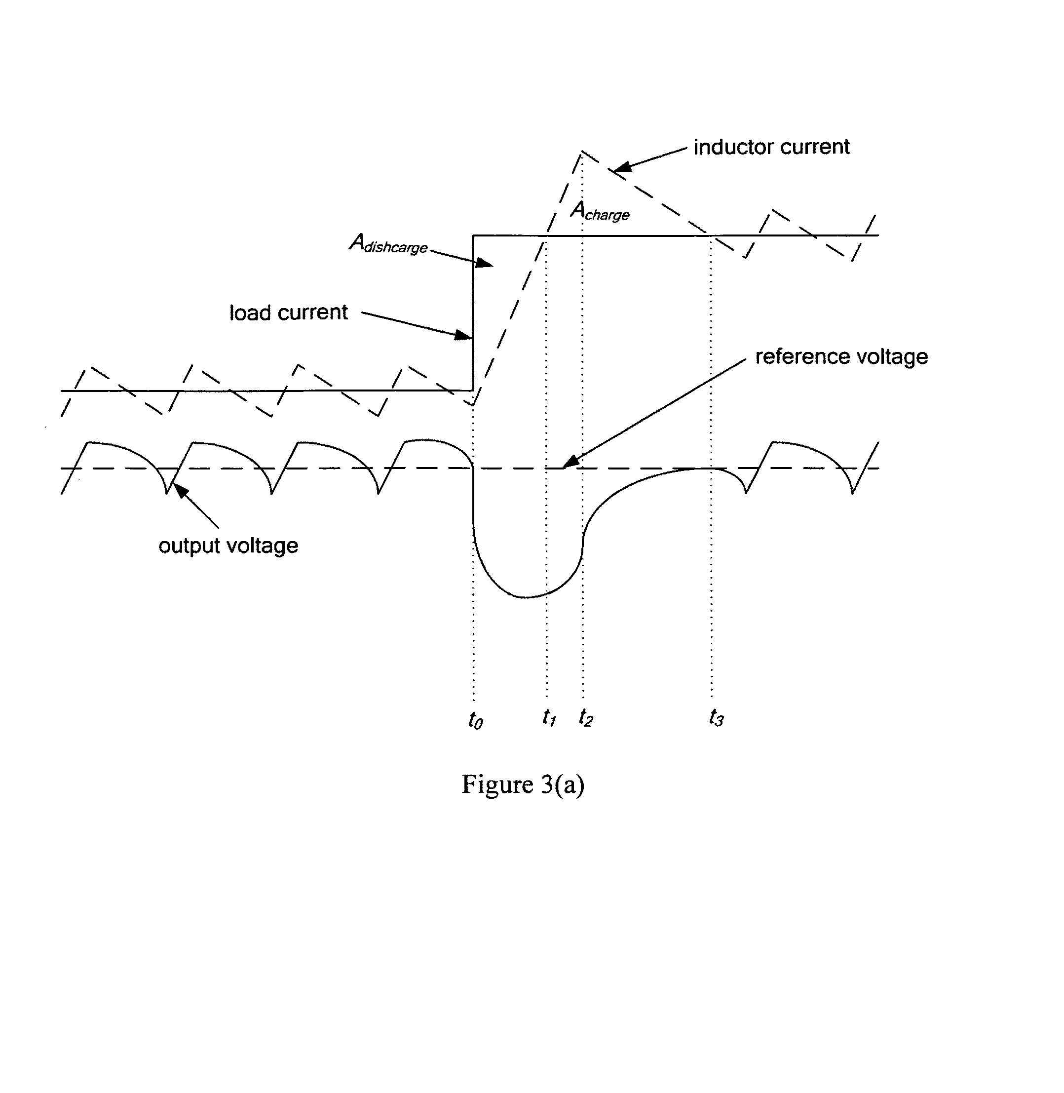
[0155]The principle of capacitor charge balance may be used to ensure that the output voltage and the inductor current reach steady state simultaneously and in the minimum possible time. FIG. 14 shows the transient response to a negative current step under the proposed control method.
[0156]It is observed in FIG. 14 that the capacitor charge portion Acharge may now be approximated by equation (21).
[0157]Acharge=∫t0t1a[iL(t)-iaux_avg-io2]ⅆt(21)
[0158]Thus Acharge, and subsequently the voltage overshoot, is significantly reduced due to the current in the auxiliary branch. It is apparent in FIG. 14 that the topology can be controlled effectively by the abovementioned control method with minor modifications. In order for the control method to function correctly, it must detect the crossover point of iL−iaux—avg−io, and the crossover point of iL−io. At t1b, when the iL−io crossover point is detected, the auxiliary circuit is disabled; how...
example 2
Simplified Auxiliary Branch Controller
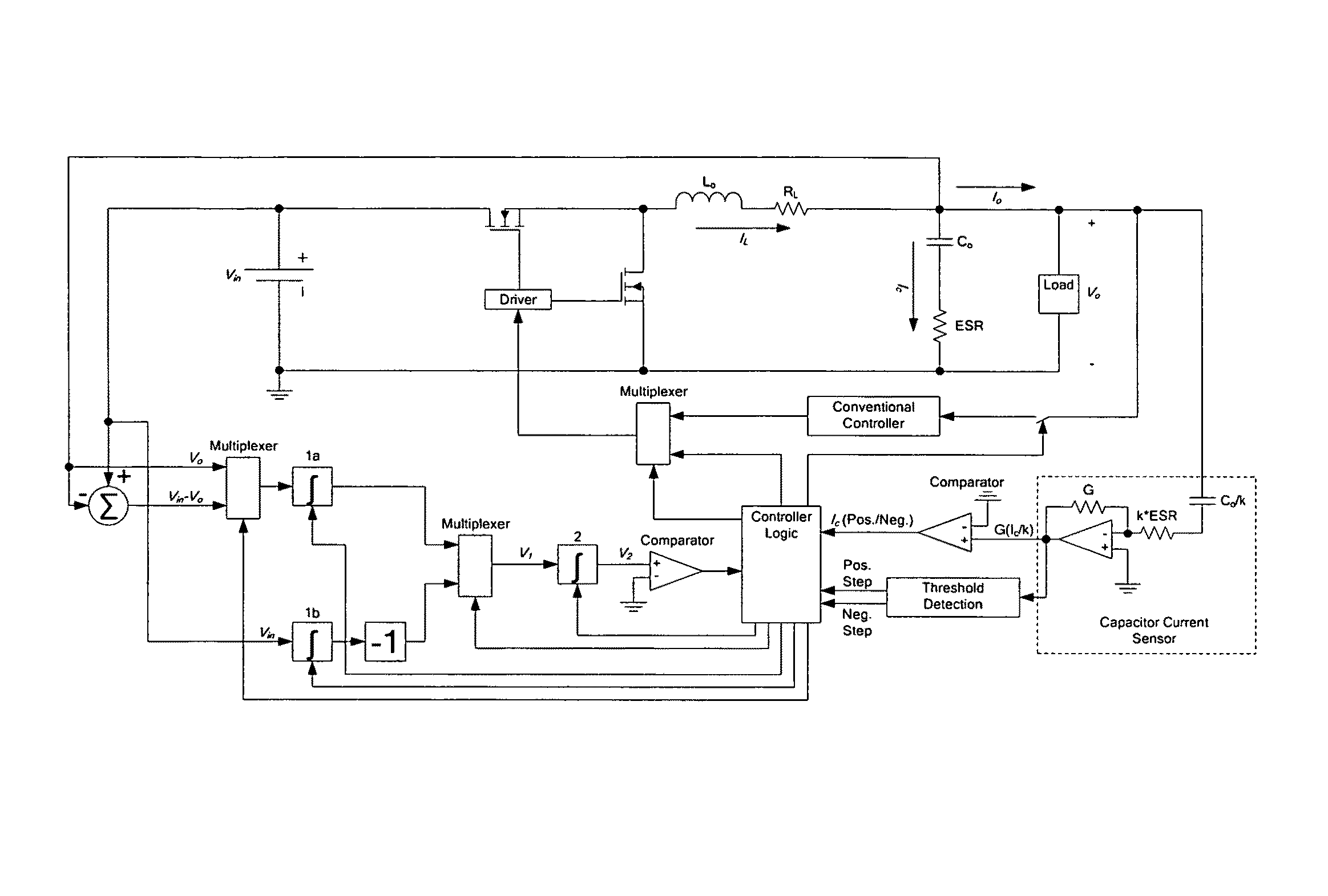
[0163]The above-mentioned controller may be greatly simplified by slightly sacrificing settling time. The simplified controller functions similarly to the controllers described above; however, it does not employ charge balance techniques, and at the point when the inductor current equals the new load current, the auxiliary branch is disabled and the control is returned to the conventional controller (e.g., voltage mode, current mode, or hysteresis mode controller). This method eliminates the need for integrators or an extra comparator. FIGS. 18(a) and (b) show block diagrams of two embodiments of such a simplified controller. In FIG. 18(a), connections shown in dashed lines are optional.
[0164]To reduce the impact of high frequency output voltage ripple caused by the equivalent series inductance (ESL) of the output capacitor, a low-pass filter (with corner frequency set below the auxiliary switching frequency) may be placed at the output of the a...
example 3
Auxiliary Branch Controller with Variable Auxiliary Current
[0177]To prevent a voltage undershoot after the initial voltage overshoot, the auxiliary current may be controlled as shown in FIG. 19. This method eliminates the possibility of a voltage undershoot at the expense of settling time. As shown in FIG. 19, at time t1, the auxiliary current level is reduced such that it equals iL−io2. The auxiliary current level may be varied by controlling the auxiliary current reference with the output of the capacitor current sensor. This operation causes the output voltage to be relatively constant for time period t1 to t2. At time t2, the conventional controller resumes control.
PUM
 Abstract
Description
Claims
Application Information
 - R&D
- Intellectual Property
- Life Sciences
- Materials
- Tech Scout
- Unparalleled Data Quality
- Higher Quality Content
- 60% Fewer Hallucinations
Browse by: Latest US Patents, China's latest patents, Technical Efficacy Thesaurus, Application Domain, Technology Topic, Popular Technical Reports.
© 2025 PatSnap. All rights reserved.Legal|Privacy policy|Modern Slavery Act Transparency Statement|Sitemap|About US| Contact US: help@patsnap.com


