
Joist hanger for ICF wall systems

a technology of icf wall and joist hangers, applied in the direction of walls, structural elements, building components, etc., can solve the problems of serious damage to the bi-directional load transfer capability of the hanger assembly, add to the total time and cost of building construction, and difficult to embed beams and joists in concrete walls formed using icf systems, etc., to achieve the effect of strengthening the anchorag

Inactive Publication Date: 2011-11-08
KITTLITZ LAVERN +1
View PDF14 Cites 11 Cited by
  • Summary
  • Abstract
  • Description
  • Claims
  • Application Information

AI Technical Summary

Benefits of technology

"The present invention provides a hanger that can support joists or beams in concrete walls made using insulated concrete formwork (ICF) systems. The hanger has a unique design that allows it to be easily mounted to the ICF wall-forming system and supports the joist or beam through direct compression without the need for fasteners. The hanger has inner and outer sections and a vertical leg that demarcates the side plates. The hanger can be used to transfer vertical reactions of the joist or beam into the concrete wall. The invention also provides methods for using the hanger to support joists or beams in ICF-formed concrete walls."

Problems solved by technology

These conventional wall insulation methods and systems add to the total time and cost of building construction.
However, it is somewhat difficult to embed beams and joists in concrete walls formed using ICF systems.
This would typically require cutting out sections of insulation to accommodate the beams and joists, and in some cases temporary shoring may be needed because the ICF panels may not be strong enough to support the weight of the embedded beams and joists during wall construction.
However, all load transfer in such hanger systems is by way of shear across the fasteners.
If the fasteners are corroded, insufficiently tight, or installed in oversized holes, the hanger assembly's bi-directional load transfer capability can be seriously compromised.

Method used


Image

  • Joist hanger for ICF wall systems
  • Joist hanger for ICF wall systems
  • Joist hanger for ICF wall systems

Examples


Embodiment Construction

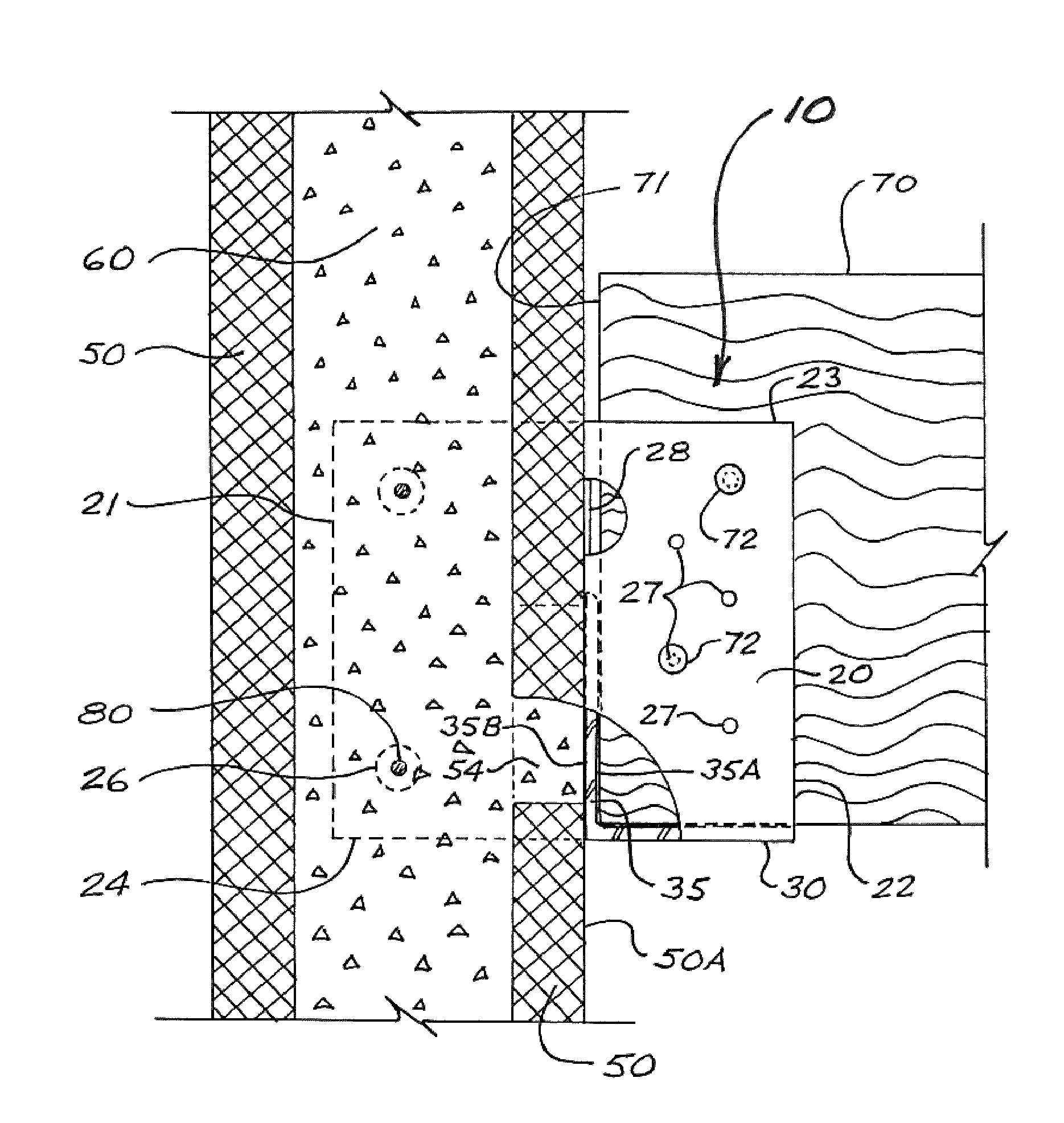
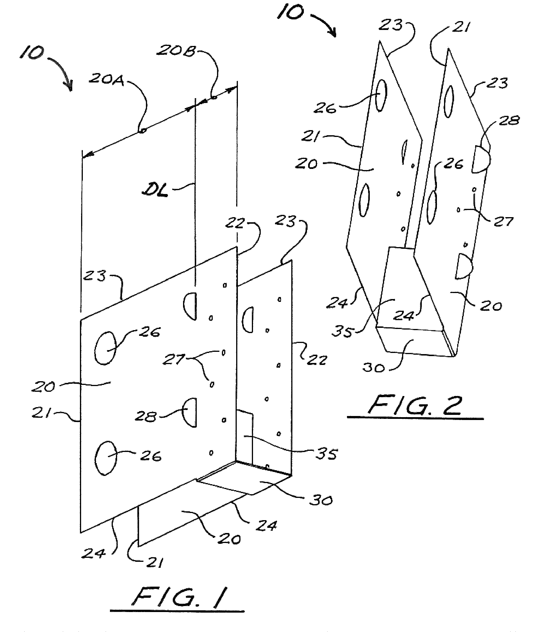
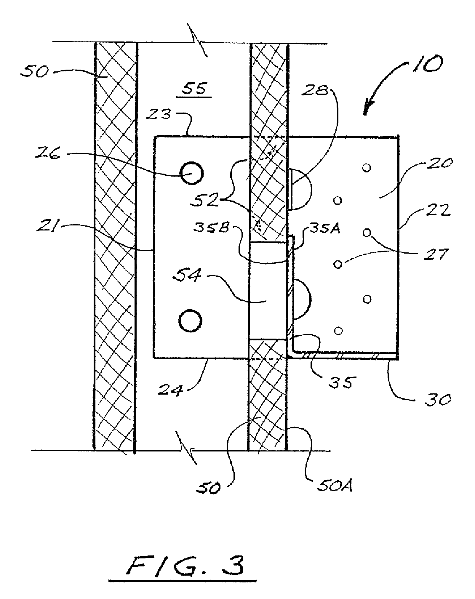
FIGS. 1 and 2 are isometric views of an ICF joist hanger in accordance with a first embodiment of the present invention, in the form of a one-piece joist hanger 10 having:a pair of spaced side plates 20, each having an inner edge 21, an outer edge 22, an upper edge 23, and a lower edge 24, with each side plate 20 being subdivided into an inner section 20A and an outer section 20B (by a notional and typically vertical demarcation line DL); anda generally L-shaped support member comprising:a base leg 30 extending widthwise between the lower edges 24 of outer sections 20B of side plates 20; andas vertical leg 35 extending upward from base leg 30 along demarcation line DL, and having an outer face 35A and an inner face 35B.

In typical cases, vertical leg 35 will be perpendicular to base leg 30, and also perpendicular to both side plates 20 (which in turn will be parallel to each other in typical cases). In special cases, however, vertical leg 35 may be other than perpendicular to base le...


PUM


Abstract

A hanger for supporting joists or beams in insulated concrete formwork (ICF) systems has two parallel side plates having inner and outer sections, plus an L-shaped support member comprising a horizontal leg extending between the lower edges of the outer sections of the side plates, and an upward-extending vertical leg which demarcates the inner and outer side plate sections. The inner sections of the side plates are passed through slits in one insulation panel of an ICF wall-forming system, until the support member's vertical leg abuts the outer face of the insulation panel, leaving the side plate inner sections extending partially into the formwork cavity. The joist or beam to be supported may be set on the horizontal leg of the support member either before or after the concrete wall is cast. Preferably, an cut-out is made in the insulation panel behind the vertical leg of the support member to allow concrete to flow against the vertical leg and the supported joist or beam is cut for a close fit against the vertical leg, such that external horizontal loads on the wall can pass into the joist or beam by direct compression.

Description

FIELD OF THE INVENTIONThe present invention relates in general to support hardware for structural joists an beams, and relates in particular to joist and beam hangers for use in association with concrete walls constructed using insulated concrete formwork systems.BACKGROUND OF THE INVENTIONIt is increasingly common for both below-grade and above-grade concrete walls to be constructed using insulated concrete formwork (or “ICF”) systems. In conventional concrete wall-forming systems, a pair of wood or metal form panels are set up at a spacing corresponding to the desired thickness of the finished wall, thus creating a cavity between the panels. As necessary or desired, steel reinforcing bars are positioned within the formwork cavity. The form panels are secured in position using form ties extending between the form panels, and / or by means of external temporary bracing. Fluid concrete is then introduced into the formwork cavity. After the concrete has cured sufficiently, the formwork ...

Claims


Application Information

Patent Timeline
Patent Type & Authority Patents(United States)
IPC IPC(8): E04B1/38
CPCE04B1/2612E04B2/8629
Inventor KITTLITZ, LAVERNKITTLITZ, RUBYANN
Owner KITTLITZ LAVERN
Learn More