
Socket and spigot type pipeline connector with anchoring structure

A pipe interface, socket-type technology, applied in the direction of pipes/pipe joints/fittings, through components, mechanical equipment, etc., can solve the problems of anchor teeth breakage, inconvenient optimization design, limiting pipeline transportation capacity, etc., to reduce meshing. The effect of tooth fracture, improving anchoring reliability, and safe anchoring effect

Active Publication Date: 2016-01-13
XINXING DUCTILE IRON PIPES CO LTD
View PDF11 Cites 10 Cited by
  • Summary
  • Abstract
  • Description
  • Claims
  • Application Information

AI Technical Summary

Problems solved by technology

In prior art 4, when the interface moves relatively, the other support point of the anchor is in contact with the wall of the socket pipe. When the interface deflects when the foundation subsides, the anchor cannot adapt to the deflection of the interface. When the deflection reaches a certain angle , will cause the fracture of the anchor teeth
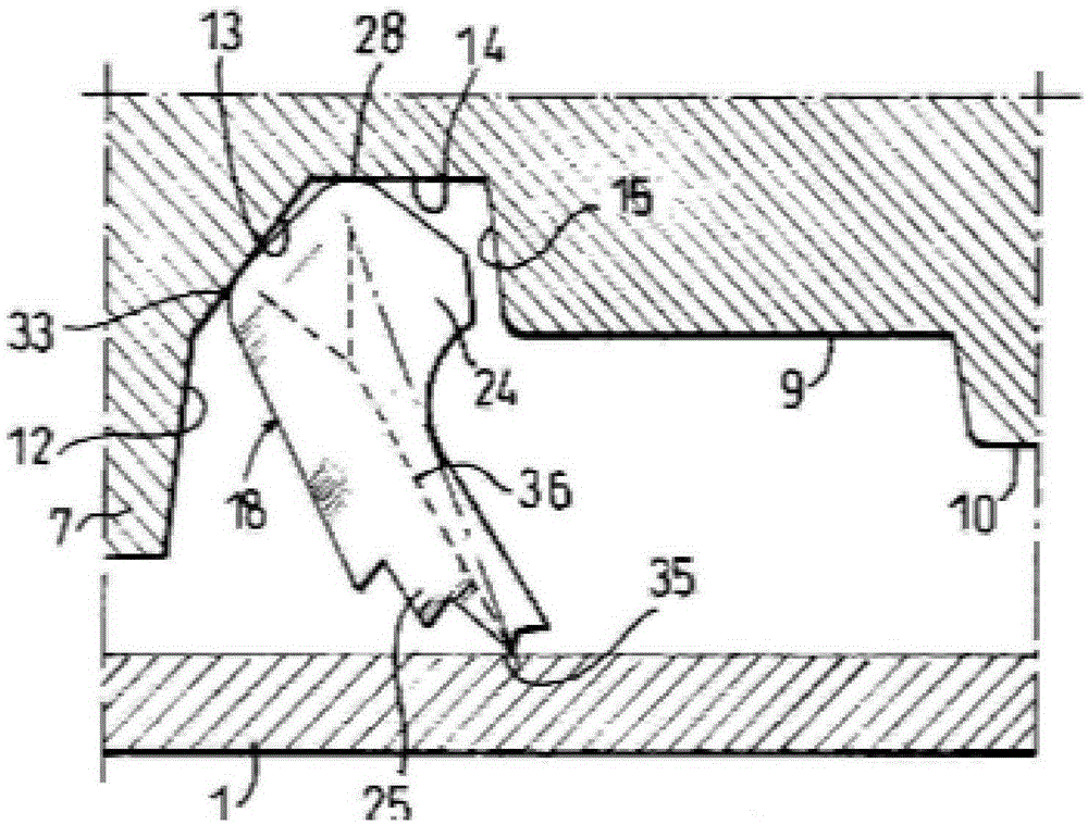
[0008] (5) Prior art 5 discloses an anchoring seal with an anchoring function, the publication number is US6688652B2, see the attached Figure 1e , in prior art 5, when the anchor structure is stressed, the two support points are in contact with the wall of the socket, and the contact form is point-to-surface contact. When the internal pressure of the pipe wall increases, the anchor cannot Rotate, the teeth of the anchor will continue to penetrate into the pipe wall, resulting in the rupture of the pipe wall and water seepage at the interface.
[0010] (1) It is not conducive to improving the reliability of anchoring
In the process of changing the support position, the multi-point support of the anchors occurs. In this case, the pipe wall and the anchors are affected by the shear force, which may easily cause the pipe wall to crack or the anchor to break.
[0011] (2) It is not conducive to prolonging the life of the structure
Sealed pipes are prone to leaks due to broken anchors or partial material failure, resulting in the need for repair or replacement, resulting in increased maintenance costs
[0013] (4) Not conducive to structural optimization simulation
The change of the support position depends on the relative movement of the socket and the socket, and the relative movement of the two depends on the external environment such as the foundation. Therefore, the unpredictability of the external environment leads to the uncertainty of the support position, which in turn leads to the uncertainty of the pipe wall in the design stage. The numerical simulation is quite different from the real situation, which is not conducive to the design optimization of the overall structure of the socket-type pipe joint with anchoring structure, thus affecting the improvement of the overall performance and bringing inconvenience to the optimization design
[0014] (5) It is not conducive to increasing the pipeline transportation capacity
The size of the pipe diameter determines the transportation capacity of the pipeline structure. Due to the instability of the force caused by its multiple supports and the difficulty of simulation, etc., in order to ensure the reliability, stability, safety and life of the structure, the pipe diameter size It has been difficult to improve significantly. At present, the diameter of the socket-type pipe joint of the anchor structure in the market is only DN200 and below, which greatly limits the transportation capacity of the pipeline.

Method used


Image

  • Socket and spigot type pipeline connector with anchoring structure
  • Socket and spigot type pipeline connector with anchoring structure
  • Socket and spigot type pipeline connector with anchoring structure

Examples


Embodiment Construction

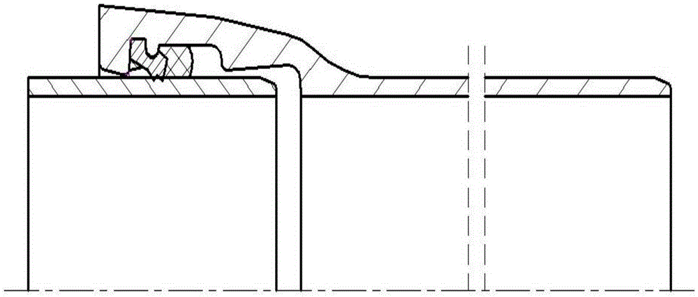
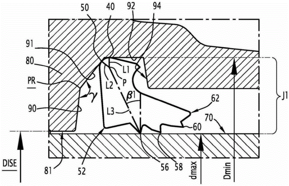
[0064] combine Figure 2-5 As shown, the socket-and-socket pipe connection with anchoring structure of the present invention includes a socket 67, a socket 66, a seal 65 between the socket 67 and the socket 66 for sealing and locking the pipe connection, wherein the socket 67 and The sockets 66 belong to two pipes respectively, and the two pipes are plugged in through the sockets and the sockets.

[0065] The socket 67 includes an annular groove 5 which is sequentially connected and defined by the first annular vertical wall 1, the tapered wall 2, the cylindrical inner wall 3 and the second annular vertical wall 4. The annular groove 5 is used to support the sealing member 65, and the sealing member 65 includes an elastic material ring 69 and a plurality of anchors 68 embedded therein, and a plurality of anchors 68 can be annular and embedded in the elastic material ring 69 at equal intervals. Of course, a plurality of anchors 68 can also be annular and not Elastomeric rings ...


PUM

PropertyMeasurementUnit
Depthaaaaaaaaaa

Abstract

The invention relates to a socket and spigot type pipeline connector with an anchoring structure. The socket and spigot type pipeline connector with the anchoring structure is used for continuous nodular cast iron pipes. By means of the socket and spigot type pipeline connector, anchoring reliability can be improved, structural service life can be prolonged, pipeline maintaining cost can be reduced, optimization and simulation of the connector structure can be performed easily, and pipeline transporting capacity is improved. The socket and spigot type pipeline connector comprises a socket, a spigot and a sealing piece which is arranged between the socket and the spigot and used for sealing and locking the pipeline connector. The socket comprises an annular groove which is formed by sequentially connecting a first annular vertical wall, a conical wall, a cylindrical inner wall and a second annular vertical wall in a defined manner. The sealing piece comprises an elastic material ring and a plurality of anchoring pieces embedded in the elastic material ring. Each anchoring piece comprises a head and a plurality of meshing teeth. Each anchoring piece is provided with a rotating circle center. The portion, connected with the annular groove in an abutting manner, of each head is an arc supporting face. The abutting joint area of each arc supporting face and the annular groove is located on the joint of the first annular vertical wall and the conical wall.

Description

technical field [0001] The invention relates to a socket-type pipe joint, in particular to a socket-type pipe joint with an anchoring structure for connecting ductile iron pipes. Background technique [0002] Ductile iron pipes are used in the field of water and gas transmission. The two ends of the ductile iron pipes are sockets and sockets respectively. The main connection method of two ductile iron pipes in the pipeline is: the socket of one pipe and the socket of the other pipe Plug-in butt, and install a sealing rubber ring between the socket and the socket. Ductile iron pipes are supported by soil or other supports during use. In areas with poor geological conditions or prone to earthquakes, the supporting soil or other supports are prone to displacement, which can easily lead to plug-in socket and socket parts. If the axial relative movement or tilting movement opposite to the installation direction is severe, the structure may lose its sealing effect and cause water...

Claims


Application Information

Patent Timeline
IPC IPC(8): F16L25/10F16L25/06
CPCF16L25/06F16L25/10
Inventor 李成章李军申勇徐军张涛左超刘静时文博车蕾
Owner XINXING DUCTILE IRON PIPES CO LTD
Learn More