Receiver and electronic device
a technology of electronic devices and receivers, applied in the field of receivers, can solve problems such as the inability to detect a defect in a pulse, the deterioration of the quality of the reproduced sound, and the reduction of the number of components, so as to reduce the discomfort of hearing
- Summary
- Abstract
- Description
- Claims
- Application Information
AI Technical Summary
Benefits of technology
Problems solved by technology
Method used
Image
Examples
embodiment 1
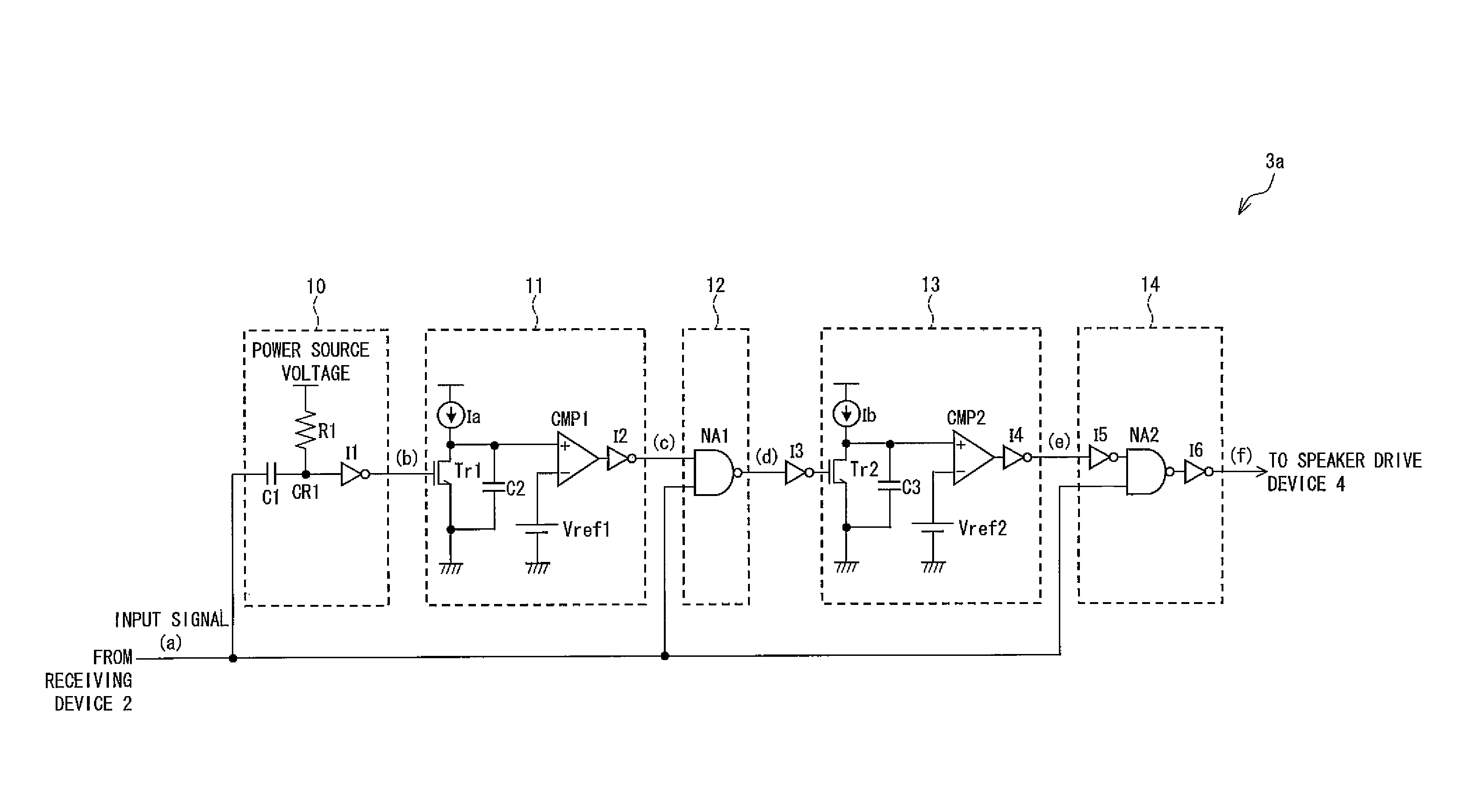
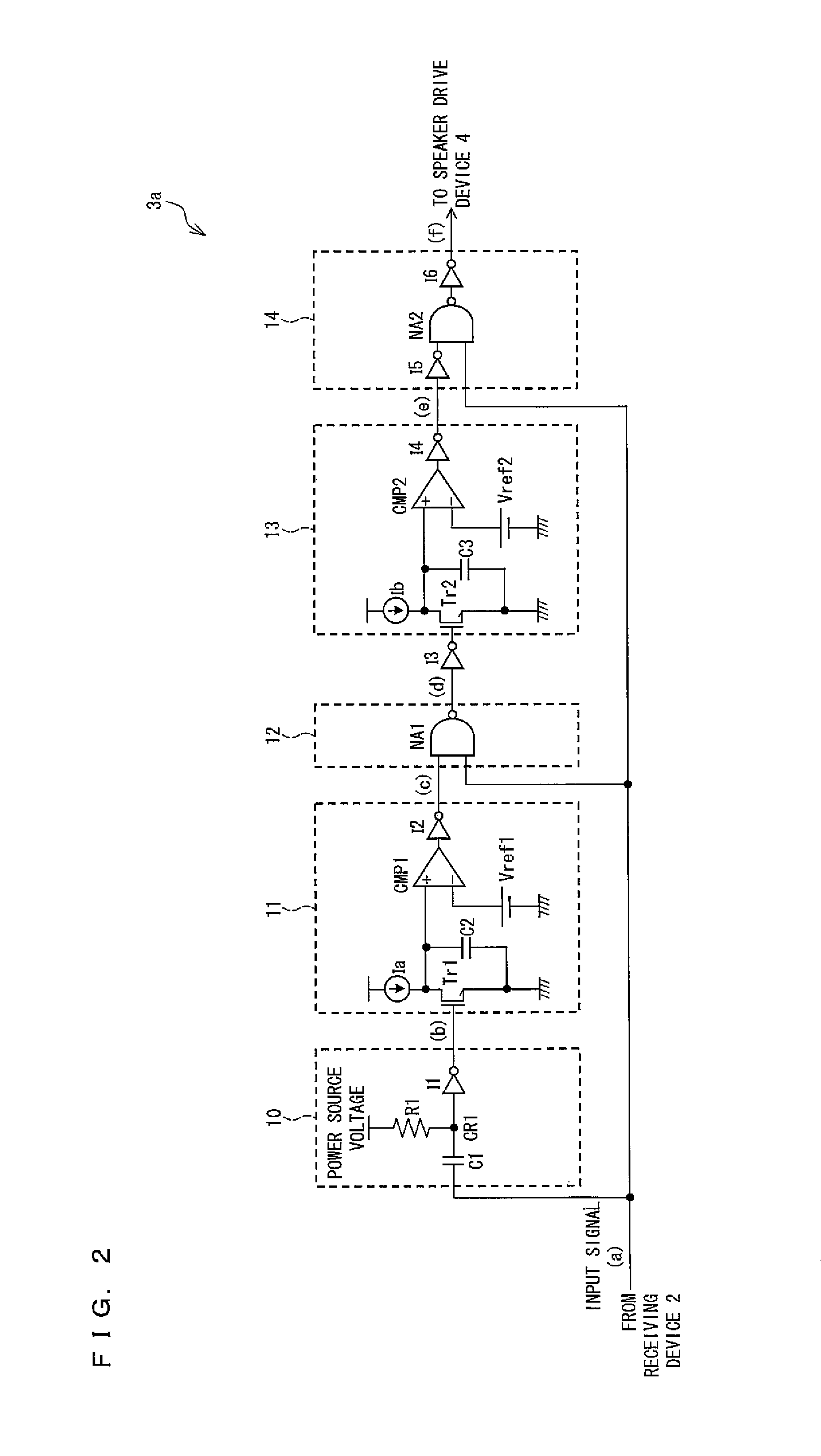
[0080]The following will discuss an embodiment of the present invention with reference to FIG. 1 through FIG. 6.
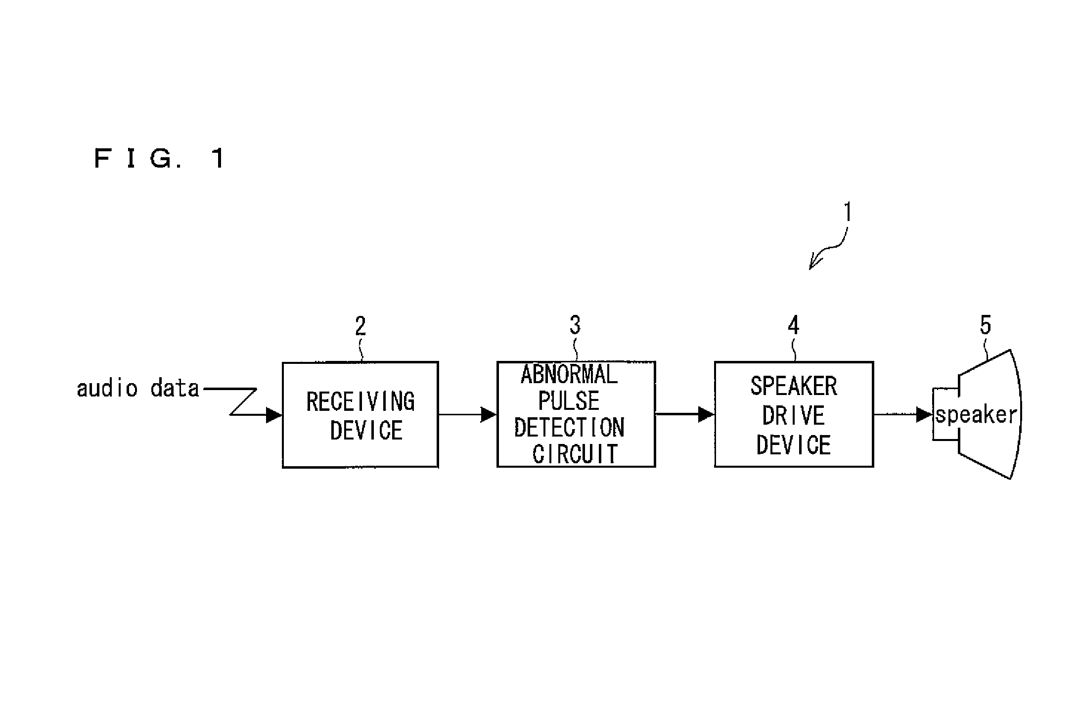
[0081]FIG. 1 is a block diagram showing the outline of a receiver of the present invention.
[0082]An optical receiver (receiver) 1 shown in FIG. 1 is, for example, a receiver provided in an electronic device which receives in a wireless manner an optical signal transmitted by a transmission system adopting infrared light or light, and includes a receiving device 2, an abnormal pulse detection circuit (abnormal pulse detection means) 3, a speaker driver 4, and a speaker 5.
[0083]The receiving device 2 receives in a wireless manner audio data supplied from, for example, an optical transmitter (not illustrated), and amplifies the received audio data. Then the receiving device 2 sends the amplified audio data to the abnormal pulse detection circuit 3. It is noted that in the present invention the receiving device 2 does not have to have the function of amplifying audio data. It ...
embodiment 2
[0185]The following will describe another embodiment of the present invention with reference to FIGS. 7 through 11. By the way, members having the same functions as those already described with reference to figures are given the same numbers, so that the descriptions are omitted for the sake of convenience.
[0186]FIG. 7 is a block diagram showing another example of the abnormal pulse detection circuit. Being similar to the abnormal pulse detection circuit 3a shown in FIG. 2, the abnormal pulse detection circuit (abnormal pulse detection means) 3b shown in FIG. 7 is suitably used as an abnormal pulse detection circuit 3 in the optical receiver 1 shown in FIG. 1. The abnormal pulse detection circuit 3b shown in FIG. 7 receives a positive-logic digital signal as an input signal.
[0187]Being similar to the abnormal pulse detection circuit 3a shown in FIG. 2, the abnormal pulse detection circuit 3b shown in FIG. 7 is an example suitable for the detection of an abnormal pulse which occurs i...
embodiment 3
[0254]The following will describe another embodiment of the present invention with reference to FIGS. 12 through 14. By the way, members having the same functions as those already described with reference to figures are given the same numbers, so that the descriptions are omitted for the sake of convenience.
[0255]FIG. 12 is a block diagram showing a further example of the abnormal pulse detection circuit. Being similar to the abnormal pulse detection circuit 3a shown in FIG. 2 and the abnormal pulse detection circuit 3b shown in FIG. 7, the abnormal pulse detection circuit (abnormal pulse detection means) 3c shown in FIG. 12 is suitably used as the abnormal pulse detection circuit 3 in the optical receiver 1 shown in FIG. 1. The abnormal pulse detection circuit 3c shown in FIG. 12 receives a negative-logic digital signal as an input signal.
[0256]The abnormal pulse detection circuit 3c shown in FIG. 12 is an example suitable for detecting in the input signal an abnormal pulse (e.g. p...
PUM
 Abstract
Description
Claims
Application Information
 - R&D
- Intellectual Property
- Life Sciences
- Materials
- Tech Scout
- Unparalleled Data Quality
- Higher Quality Content
- 60% Fewer Hallucinations
Browse by: Latest US Patents, China's latest patents, Technical Efficacy Thesaurus, Application Domain, Technology Topic, Popular Technical Reports.
© 2025 PatSnap. All rights reserved.Legal|Privacy policy|Modern Slavery Act Transparency Statement|Sitemap|About US| Contact US: help@patsnap.com


