Eureka AIR delivers breakthrough ideas for toughest innovation challenges, trusted by R&D personnel around the world.

Thin camera and associated methods

a camera and lens technology, applied in the field of thin cameras, can solve the problems of increasing the difficulty of optical imaging systems to deliver the required mtf, increasing the lens diameter, and relatively thick cameras

Inactive Publication Date: 2011-11-01
FLIR SYSTEMS TRADING BELGIUM BVBA
View PDF60 Cites 50 Cited by
  • Summary
  • Abstract
  • Description
  • Claims
  • Application Information

AI Technical Summary

Benefits of technology

[0017]It is yet another feature of an embodiment of the present invention to provide a thin camera including baffles blocking stray light.
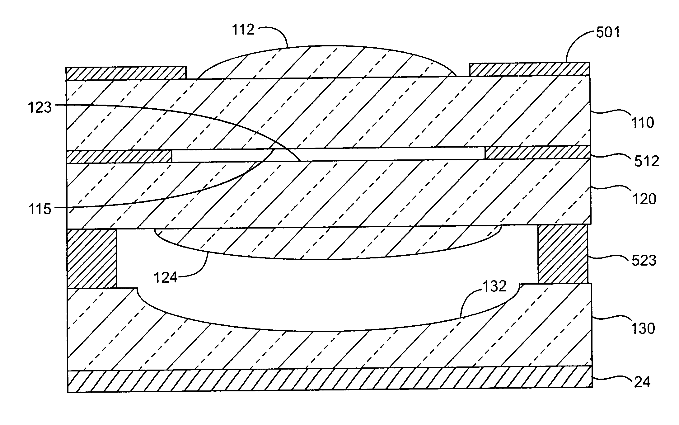
[0027]At least one of the above and other features and advantages of the present invention may be realized by providing a method of making a camera, the method including forming a convex refractive element on a first planar substrate, forming a concave refractive element on a second planar substrate, providing a separator between the first and second planar substrates, the separator providing an air gap between convex refractive element and the concave refractive element, providing a third planar substrate having a detector array thereon, the third planar substrate being closer to the second planar substrate than the first planar substrate, and securing the first to third substrates, along a z-axis, wherein the z axis is perpendicular to a plane of the detector array.

Problems solved by technology

However, this camera is relatively thick.
The problem is that as px and py are scaled down, higher MTF is required by the optical imaging system.
It becomes harder and harder to make optical imaging systems capable of delivering the required MTF as the pixel size is scaled down.
In addition, as the pixel size is reduced, other issues become more predominant including color crosstalk, electrical crosstalk, and reduced fill factor.
However, the use of compound eye image capturing is computationally intensive and it is difficult to achieve a resolution equal or close to that of the number of pixels in the sensor array for the entire composite image.
One reason for the low resolution achieved with the compound eye image capturing approach, is that a large number of lenses are used, placing practical limits on the resolution for each sub-camera.
In addition, the performance of each sub-camera is also typically low due to the approach taken.
Due to the shortness of the focal length of these systems and the thickness of typical lens substrates, there is no room in such systems to place multiple compound element lens systems in the space between the entrance pupil of the lens system and the signal separator.

Method used


Image

  • Thin camera and associated methods
  • Thin camera and associated methods
  • Thin camera and associated methods

Examples


Embodiment Construction

[0053]The present invention will now be described more fully hereinafter with reference to the accompanying drawings, in which preferred embodiments of the invention are shown. The invention may, however, be embodied in different forms and should not be construed as limited to the embodiments set forth herein. Rather, these embodiments are provided so that this disclosure will be thorough and complete, and will fully convey the concept of the invention to those skilled in the art.

[0054]In the drawings, the thickness of layers and regions may be exaggerated for clarity. It will also be understood that when a layer is referred to as being “on” another layer or substrate, it may be directly on the other layer or substrate, or intervening layers may also be present. Further, it will be understood that when a layer is referred to as being “under” another layer, it may be directly under, or one or more intervening layers may also be present. In addition, it will also be understood that wh...


PUM


Abstract

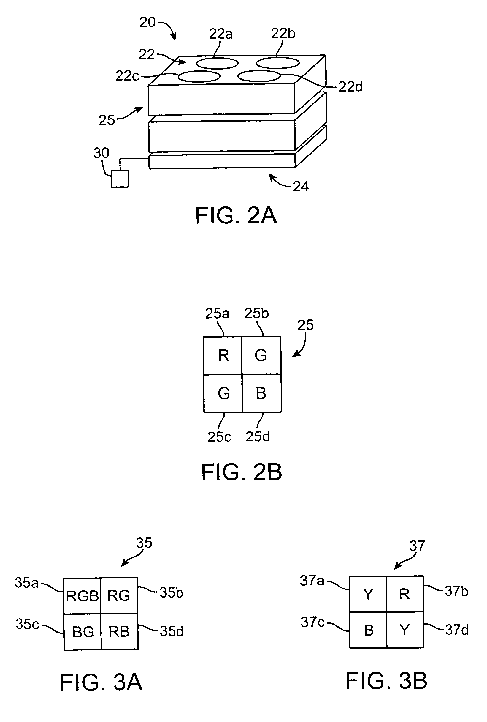
A camera includes a first substrate having a convex refractive element, a second substrate having a concave refractive element, a separation between the first to second substrates, the separation including an air gap between convex refractive element and the concave refractive element, and a third substrate having a detector array thereon, the concave refractive element being closer to the detector than the convex refractive element, at least two of the first to third substrates being secured along a z-axis, wherein the z axis is perpendicular to a plane of the detector array, e.g., at a wafer level. The convex refractive element may include a plurality of convex refractive elements, the concave refractive element may include a plurality of concave refractive elements, and the detector array may include a plurality of detector arrays, each of the plurality forming a plurality of sub-cameras.

Description

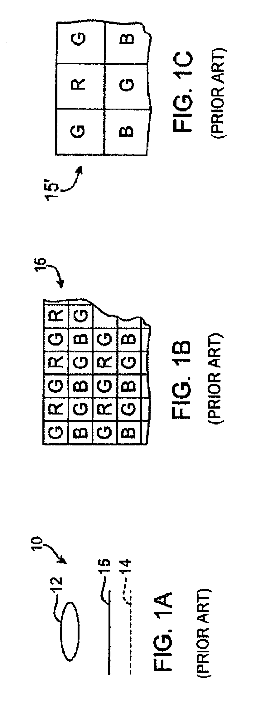
CROSS-REFERENCE TO RELATED APPLICATIONS[0001]The present invention is a continuation-in-part of commonly assigned, U.S. application Ser. No. 10 / 949,807, filed Sep. 27, 2004 now U.S. Pat. No. 7,773,143, and entitled “Thin Color Camera”, which is hereby incorporated by reference.BACKGROUND OF THE INVENTION[0002]1. Field of the Invention[0003]The present invention is directed to a thin camera. More particularly, the present invention is directed to a thin camera using color filters, a thin camera having an increased field of view and / or a thin camera that can be made on a wafer level, and associated methods.[0004]2. Description of Related Art[0005]A conventional camera 10, shown in FIG. 1A includes a lens 12 with a focal length f and a detector array 14, having a plurality of pixels. To realize color imaging, an array of filters 15 having some pattern, typically with more green filters than red or blue filters, is provided. An example of the filter array 15 is shown in FIG. 1B. Each fi...

Claims


Application Information

Patent Timeline
Patent Type & Authority Patents(United States)
IPC IPC(8): H04N5/225H01L21/00H04N9/09G02B27/10H01L31/0232H04N5/359H04N9/04
CPCG02B9/12G02B13/0035G02B13/006G02B13/0085H01L27/14625H01L27/14685H04N5/2254H04N9/045H04N23/54
Inventor FELDMAN, MICHAEL R.MORRIS, JAMES E.TEKOLSTE, ROBERT D.
Owner FLIR SYSTEMS TRADING BELGIUM BVBA
Why Eureka
Eureka Blog
Learn More