
Systems and methods of editing cells of an electronic circuit design

a technology of electronic circuit design and cell, applied in the field of electronic circuit design and manufacturing, can solve the problems of increasing the visual complexity of the design, design tools running more slowly, and existing approaches that do not permit editing of submaster content in layout editors

Inactive Publication Date: 2011-10-25
CADENCE DESIGN SYST INC
View PDF5 Cites 57 Cited by
  • Summary
  • Abstract
  • Description
  • Claims
  • Application Information

AI Technical Summary

Benefits of technology

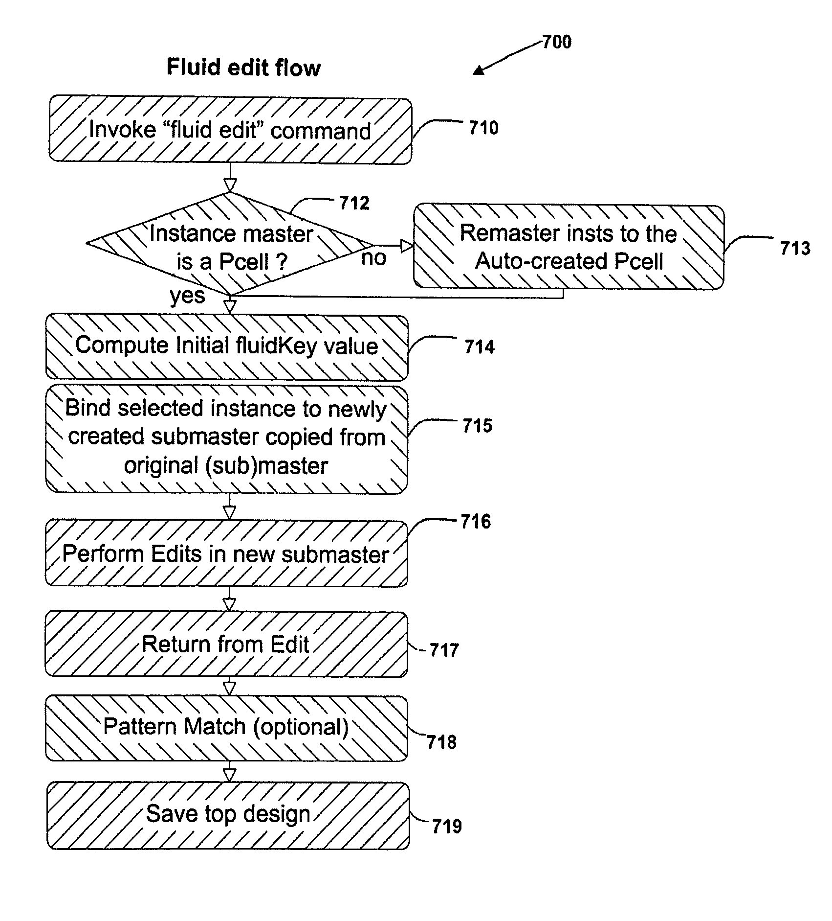
[0012]Systems and methods to enable a user to edit subMaster content of selected instances of an electronic layout design, including editing the contents of selected instances of an existing subMaster of an EDA design, generating a newSubmaster to incorporate the modified contents of the selected instances, and binding the new subMaster to the selected instances without losing the design hierarchy of the layout design. The systems and methods of the present general inventive concept can thus enable a user to edit the content of an existing subMaster associated with selected instances of the layout design, either directly from the top-level design, or by descending into the subMaster to edit shapes of existing instances from a lower-level, and then returning to the top level upon completion of the fluid edit without losing the layout design hierarchy. The present general inventive concept can be applied to achieve edits of subMaster content requested by a user, and to achieve edits performed by components of an EDA tool, for example, by using a layout compactor or design for manufacturing (DFM) hotspot repair tool.

Problems solved by technology

Attempts have been made to allow subMasters to be stored on disk, for faster opening of designs, but existing approaches do not permit editing of subMaster content in layout editors.
In contrast, flat design files (i.e., no design hierarchy) are typically very large since all of the details are included in the same level, thus increasing the visual complexity of the design and causing the design tools to run more slowly.
One drawback of existing approaches is that although they may allow a user to modify pcell parameters through stretching stretch handles and abutment, they are less than satisfactory in allowing other edits since the contents of the new sub-master are limited to what the pcell programming code is capable of generating, and is controlled by parameter modifications on the instance, with results being that only the edits that the pcell designer has built into the pcell programming code can be made.
To work around this limitation, users sometimes flatten the pcell instances throughout the layout design, but this results in losing the design hierarchy and increasing memory usage.
Accordingly, existing approaches do not enable a user to easily and efficiently make local edits of masters of instances in hierarchical designs without losing the hierarchical structure of the design, and do not allow editing of subMaster content of selected instances, to form new subMasters with different parameters, which can then be saved to disk.
Another drawback of existing approaches is that they do not allow the retention of user edits to shapes during automatic parameter modifications such as auto-abutment and stretching stretch handles.
For example, in existing approaches, users are unable to retain their edits during pcell abutment or after user-initiated changes of parameters of instances whose masters have been edited.
Another drawback of the existing approaches is that in order to make edits to one particular instance of a pcell the user must manually save a copy of the pcell master, apply their edits in the non pcell copy cellview, and then manually re-master the one instance that they wish to be affected to the new non pcell cell view they created.
Moreover, existing approaches to cell editing do not provide the ability to easily make a local edit to a single instance of a non-pcell master, if there are multiple instances of that master in the design because such edits of an existing master affect all instances.
Such limited editing capabilities of these and similar existing approaches has become a serious problem for customers, who do not want to be constrained to only those edits that the process design kit (PDK) designer has built into the respective design cell offerings.

Method used


Image

  • Systems and methods of editing cells of an electronic circuit design
  • Systems and methods of editing cells of an electronic circuit design
  • Systems and methods of editing cells of an electronic circuit design

Examples


example 1

Retaining Fluid Edits after Abutment

[0094]FIG. 8 illustrates an initial design state, where no fluid edits have been done. The relevant layout design is deslib / top / layout cellview. Here, three (3) instances of pcell moslib / mos / layout (I1, I2, and I3) have been instantiated. I1 and I2 have length parameter (L=1), while I3 has length parameter=3. Assume the default length parameter value is 0.5, and assume moslib / mos / layout pcell also has srcAbut and drainAbut boolean parameters default value set to false. Here, the parameters stored on the instance headers instHeaders may take the following values, for example:

subIH1: L=1

subIH2: L=3

[0095]FIG. 9 illustrates the design state after instance I2 has been fluid edited. In FIG. 9, the user initiates a fluid edit by selecting instance I2, and invoking the fluidEdit command (or whichever means of fluid-edit initiation the EDA tool chooses to implement). This will set the I2 fluidKey parameter to “deslib / top / layout, 1” and behind the scenes in...

example 2

Hierarchical Fluid Edits

[0104]FIG. 15 illustrates a design named (libTop, cellTop, layout) containing three instances of the same cellA, and one instance named Bt of cell cellB. CellA also contains one instance of cellB. Here, there is illustrated a defect or “hotspot” region (star) in the left bottom region of the chip labeled defect1, and a second defect in the top right region of the chip labeled defect2. The defects were identified by a DFM (design for manufacturing) hotspot analysis tool. This illustrates how fluid edits could be applied hierarchically to fix local DFM issues while retaining design hierarchy.

[0105]Suppose (libA, cellA, layout) is not a pcell, but (libB, cellB, layout) is a pcell. In order to fix defect1 in the bottom left corner of the design, a user can take the following steps. First, the user (or tool) can fluid edit the master of instance A1, and then further fluid edit the instance B. Having fixed the problem in the fluid edited instance of B, the user can...


PUM


Abstract

Systems and methods to enable a user to edit subMaster content of selected instances of an electronic layout design, including editing the contents of selected instances of an existing subMaster of an EDA design, generating a new subMaster to incorporate the modified contents of the selected instances, and binding the new subMaster to the selected instances without losing the design hierarchy of the layout design.

Description

BACKGROUND OF THE INVENTION[0001]1. Field of the Invention[0002]The present general inventive concept relates generally to the field of electronic circuit design and manufacturing, and more particularly relates to an electronic design automation (EDA) system to edit and save changes to cells of an electronic circuit design.[0003]2. Description of the Related Art[0004]Circuit designers can create a custom design of integrated circuits, printed-circuit boards, and other electronic circuit systems using electronic design automation (EDA) technologies that typically run on an operating system in conjunction with a microprocessor-based computer system or other programmable control system. For analog, RF, and mixed signal design applications, the EDA software allows a user to implement “cells” as a basic element of functionality through a layout editor implemented on a graphical user interface. A given cell may be placed, or “instanced,” many times in a layout design to accelerate the des...

Claims


Application Information

Patent Timeline
Patent Type & Authority Patents(United States)
IPC IPC(8): G06F17/50
CPCG06F17/5068G06F30/39
Inventor FERGUSON, KENNETHBISHOP, RANDYGINETTI, ARNOLDLAMANT, GILLES
Owner CADENCE DESIGN SYST INC
Learn More