
Multi-server control panel

a control panel and multi-server technology, applied in the field of virtualized hosting services, can solve the problems of spike in demand, inaccurate prediction of configuration behavior prior to deployment, and inability to meet the needs of such users,

Active Publication Date: 2011-10-25
GOOGLE LLC
View PDF32 Cites 69 Cited by
  • Summary
  • Abstract
  • Description
  • Claims
  • Application Information

AI Technical Summary

Benefits of technology

Enables users to manage server configurations efficiently, reducing waste and costs by allowing real-time adjustments to resource allocation, improving performance monitoring, and providing accurate billing based on actual usage.

Problems solved by technology

However, reporting of hosting services typically coincides with billing reporting so that users are only notified at the end of a billing period as to the performance of their system.
However, as users become more sophisticated and require more control over their hosted configurations, the services provided by such hosting services are unable to meet the needs of such users.
Additionally, since predicting behavior of a configuration prior to deployment is inaccurate at best, users require a means by which information as to their configurations is conveyed to them in real-time.
However, some users only have a small window in which to make the changes before the spike in demand is lost.
For example, a user's configuration may only experience a traffic spike that requires 40% of the processing power for only ten minutes in a day.
Therefore, to be billed based on a single resource that does not accurately reflect the usage of the configuration may be beneficial to some configurations while detrimental to others.

Method used


Image

  • Multi-server control panel
  • Multi-server control panel
  • Multi-server control panel

Examples


Embodiment Construction

[0070]In the following description, numerous details are set forth for the purpose of explanation. However, one of ordinary skill in the art will realize that the invention may be practiced without the use of these specific details. In other instances, well-known structures and devices are shown in block diagram form in order not to obscure the description of the invention with unnecessary detail.

[0071]In the discussion below, Section I provides an overview of the multi-server control panel according to some embodiments. Section II provides examples of managing servers using the multi-server control panel. Section III provides several resource utilization meters according to some embodiments.

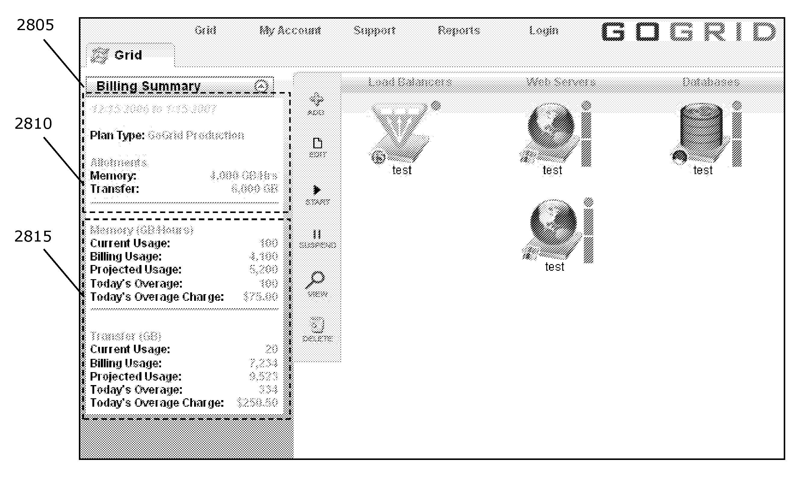
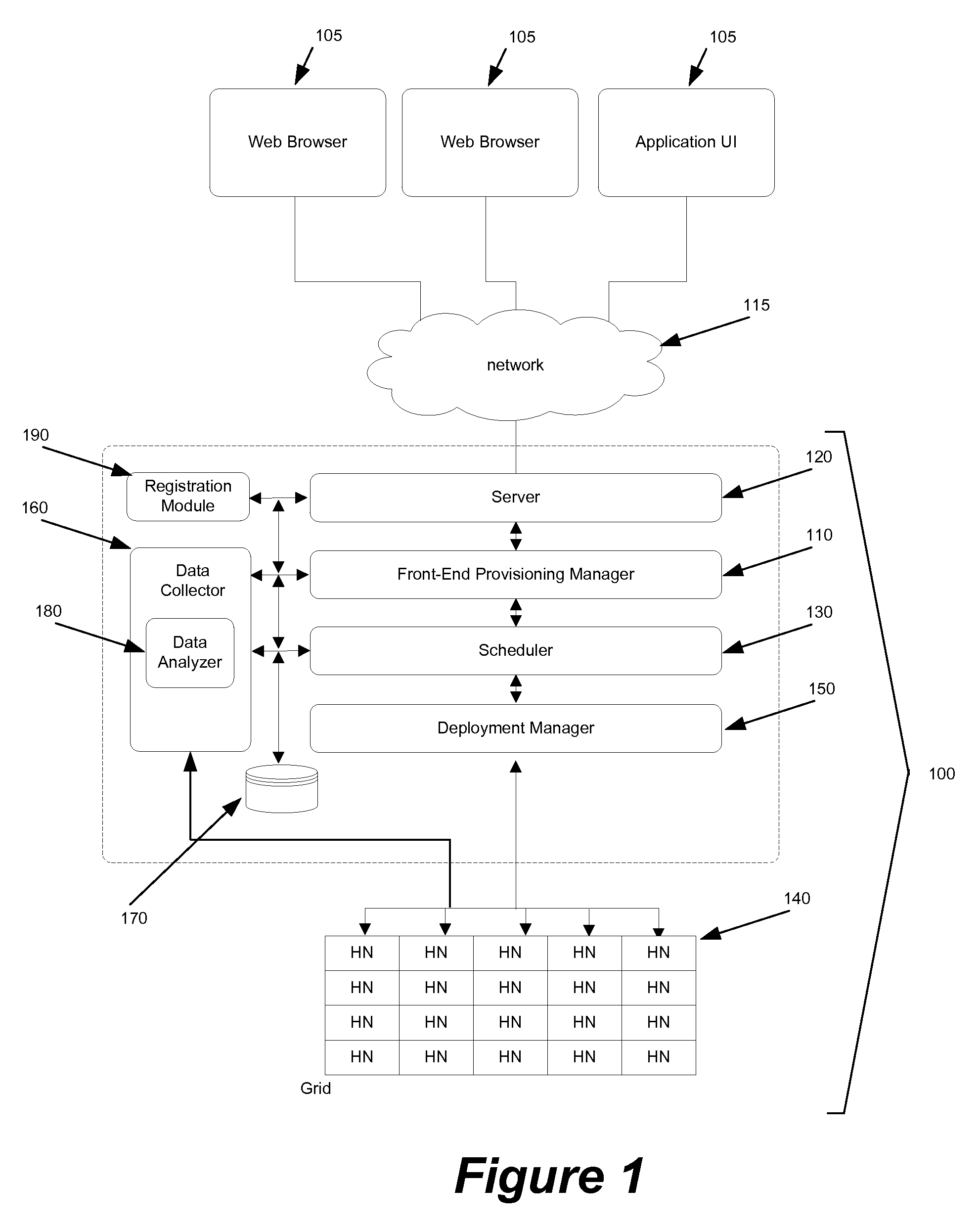
[0072]Some embodiments provide a method for automatedly receiving and provisioning a server configuration through a graphical user interface (GUI). In some embodiments, a graphical representation for the configuration is automatedly mapped and allocated to a set of hardware nodes, where the perf...


PUM


Abstract

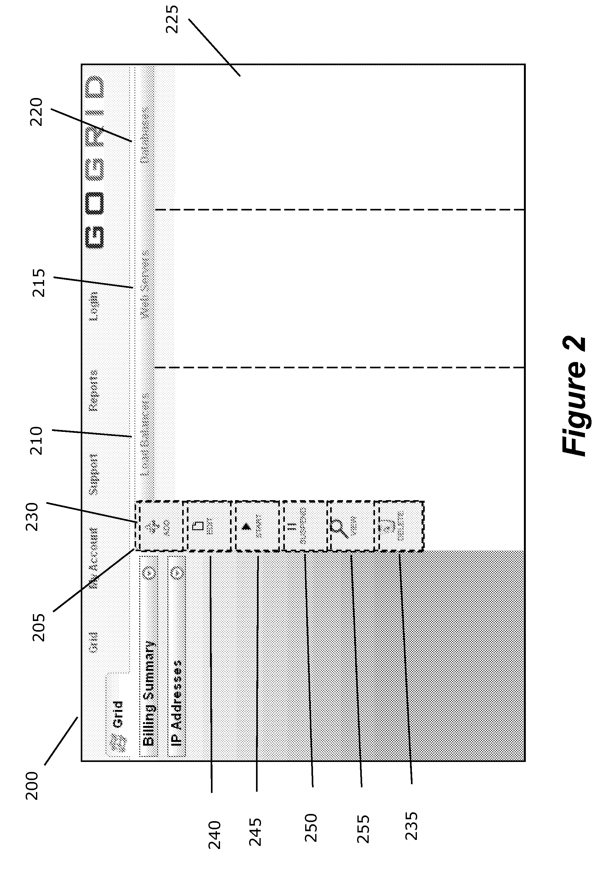
Some embodiments of the invention provide a graphical user interface for receiving a server configuration (e.g., receiving a new configuration or a modification to an existing configuration). The graphical user interface (UI) includes several UI control elements for defining components of the server configuration. It also includes a display area for displaying graphical representations of the defined components of the server configuration. Examples of control elements in some embodiments include control elements for adding, deleting, and modifying servers. In some embodiments, at least one control element is displayed when a cursor control operation is performed on the UI. The cursor control operation (e.g., a right hand click operation) in some embodiments opens a display area that shows the control element. In some embodiments, at least two different components in the server configuration correspond to two different layers (e.g., a web server layer and a data storage layer) in the server configuration. The display area of some embodiments includes multiple tiers, where each tier is for displaying graphical representation of components in a particular layer of the server configuration. At least two tiers in some embodiments are displayed simultaneously in the display area.

Description

CLAIM OF BENEFIT TO PROVISIONAL APPLICATION[0001]This application claims benefit to U.S. Provisional Application 60 / 954,310, filed Aug. 6, 2007. This provisional application is incorporated herein by reference.CROSS REFERENCE TO RELATED APPLICATIONS[0002]This Application is related to the following applications: U.S. patent application Ser. No. 11 / 834,768, filed Aug. 7, 2007; U.S. patent application Ser. No. 11 / 834,722, filed Aug. 7, 2007; U.S. patent application Ser. No. 11 / 834,726, filed Aug. 7, 2007; U.S. patent application Ser. No. 11 / 834,732, filed Aug. 7, 2007; U.S. patent application Ser. No. 12 / 185,774, filed Aug. 4, 2008; and U.S. patent application Ser. No. 12 / 353,246, filed Jan. 13, 2009, now published as U.S. Patent Publication No. 2009 / 0182605.FIELD OF THE INVENTION[0003]The present invention relates to virtualized hosting services.BACKGROUND OF THE INVENTION[0004]Hosting services provide a means whereby multiple users can implement custom server configurations without ...

Claims


Application Information

Patent Timeline
Patent Type & Authority Patents(United States)
IPC IPC(8): G06F3/00
CPCG06Q10/06G06Q30/04G06F3/0481G06F3/1224
Inventor LAPPAS, PAULKEAGY, JOHN MARTINPETERSON, NICHOLAS F.
Owner GOOGLE LLC
Learn More