Blow out protector valve employing ball baffle assembly for use with high-pressure fluids

a technology of protector valve and ball baffle, which is applied in the direction of drilling casing, drilling pipe, borehole/well accessories, etc., can solve the problems of concrete plugs in these wells and the deterioration of steel well casings, so as to prevent any blowout

Active Publication Date: 2011-10-25
WATTENBURG WILLARD HARVEY
View PDF6 Cites 11 Cited by
  • Summary
  • Abstract
  • Description
  • Claims
  • Application Information

AI Technical Summary

Benefits of technology

In one embodiment, my BOP comprises a foraminous plate or baffle that is positioned in the well pipe or a container or housing in series with the well pipe. The plate has an array of holes of a predetermined diameter. Adjacent and below the container or portion of the pipe containing this plate is a source of obturating balls that have diameters slightly greater than the holes in the plate. When a blow-out condition occurs, the balls are released under the plate so that the upward flow of fluid in the well pipe forces the balls upward against the plate where they lodge in the holes and thus cause the plate to block further fluid flow and prevent any blow-out.

Problems solved by technology

The concrete plugs in these wells and the steel well casings themselves will deteriorate with time.

Method used


Image

  • Blow out protector valve employing ball baffle assembly for use with high-pressure fluids
  • Blow out protector valve employing ball baffle assembly for use with high-pressure fluids
  • Blow out protector valve employing ball baffle assembly for use with high-pressure fluids

Examples


first embodiment

Description

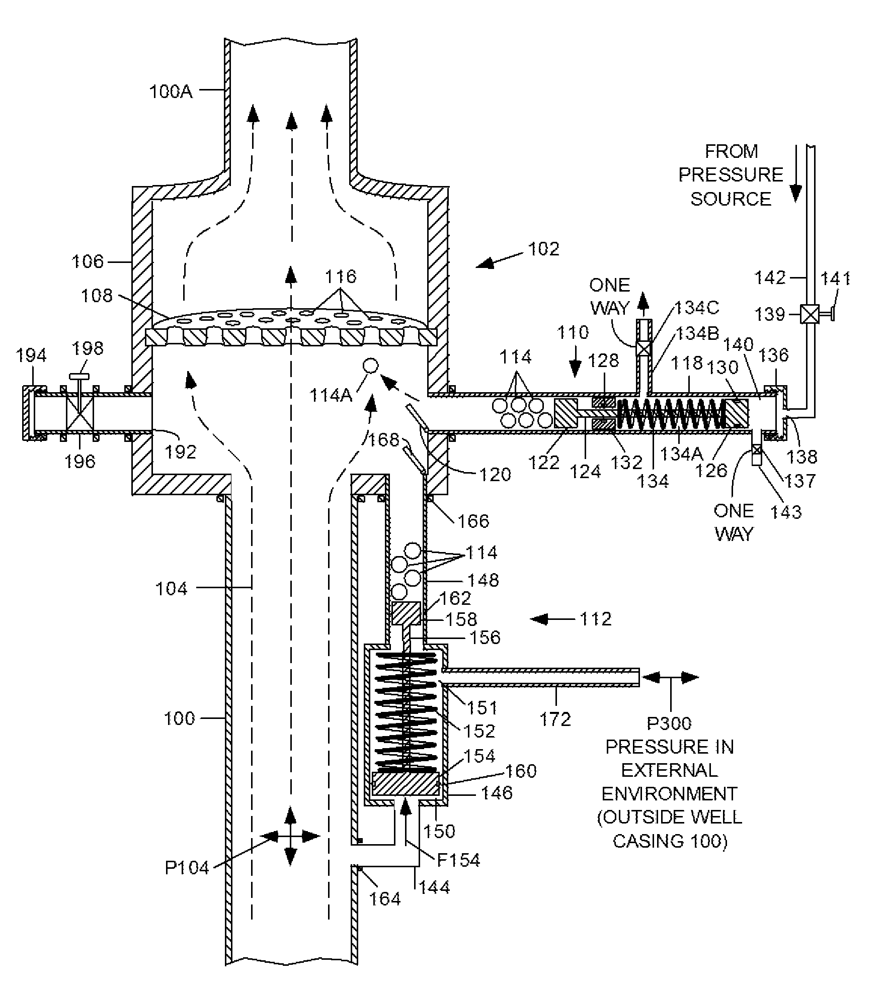
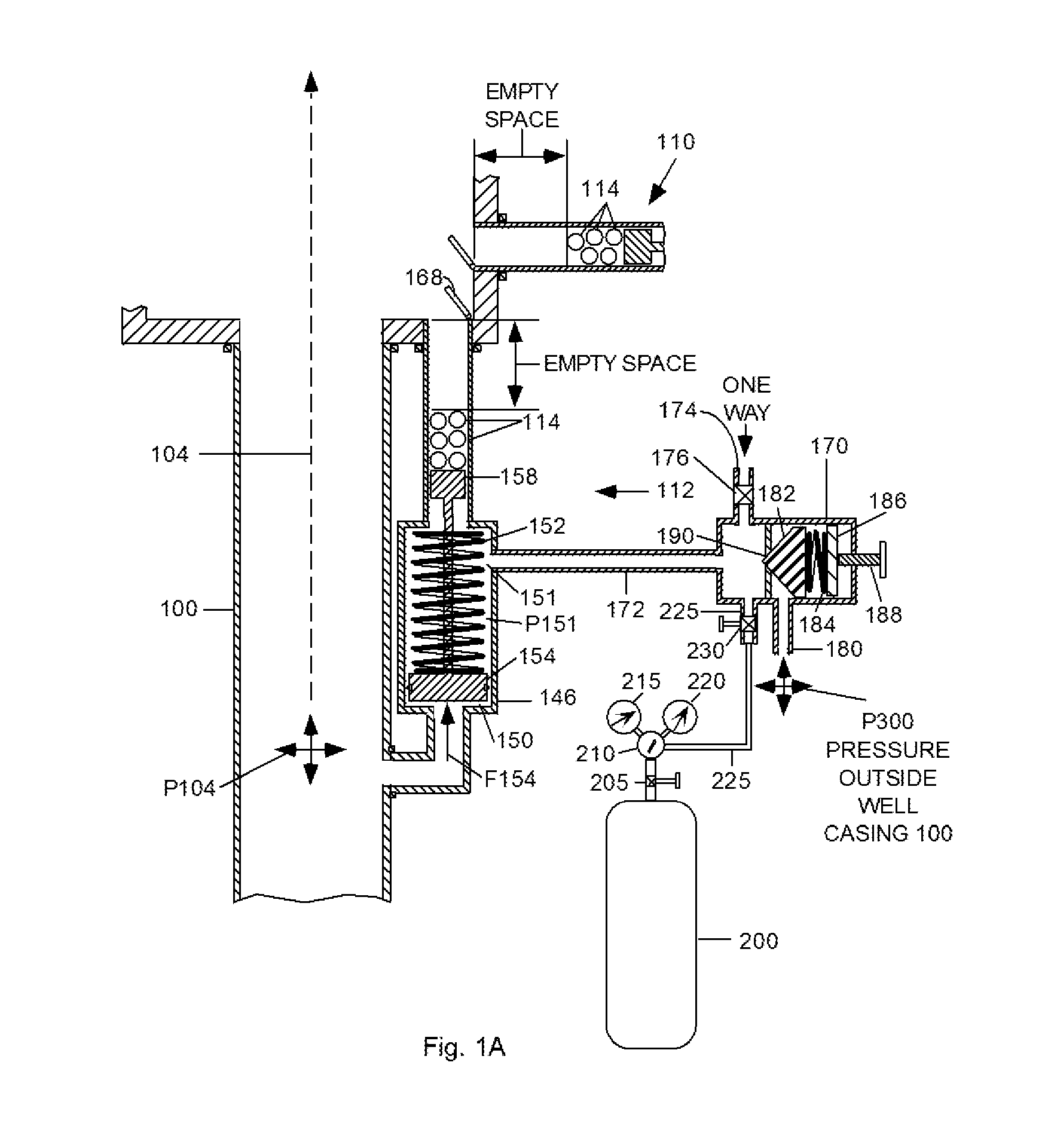
FIG. 1 is an elevated, sectional view that shows a typical riser pipe or well casing with a lower section 100 that extends downward into the well, and a section 100A that extends upward above a BBBOP 102. Pipe 100 is transporting fluids 104, indicated by dashed lines and comprising mainly oil and gas, upward from an oil well. Pipe section 100-100A can be the passageway in a conventional BOP stack mounted above a well head, or in the riser pipe above the BOP stack. Additional BOPs can be inserted in the casing above or below BBBOP 102. BBBOP 102 performs the same function as the blind ram BOP described above, i.e., it is used when the well has been drilled and producing oil and / or gas and a drill pipe is not present inside casing 100-100A.

The present embodiment comprises a housing or container 106, a foraminous baffle or plate 108, one or more ball dispensing mechanisms (BDMs) 110 and 112, each with a group of balls 114. Housing 106 has an outlet 192 with a valve 196. Valv...

second alternative embodiment

Operation Of Second Alternative Embodiment

FIG. 8 is a cross-sectional view of a portion of housing 106′ of the present embodiment during prevention of a blowout. Increased pressure and flow from the well, indicated by dashed arrows 755, has caused balls 114 to rise within housing 106′ and block holes 116′ in upper baffle wedges 600. Balls 114 were either (a) dispensed automatically by BDM 112, (b) could have been left in the space between baffles 108′ and 250′ to be deployed automatically, or (c) dispensed manually by BDM 110.

Wedges 600 have been forced upward by the well pressure, pivoting around the outer edge adjacent the inner surface of housing 106′ and moving from a downward slanted position to horizontal. The upward pressure has compressed bumpers 715, causing them to spread out and form a seal between wedges 600 and housing 106′. With wedges 600 in this position, elastomeric seals 710 impinge tightly against pipe 610, completing the sealing of the well.

When it is desired to ...


PUM


Abstract

A Ball Baffle Blowout Preventer (BBBOP) (102) or shut-off valve generally comprises a housing (106) and a baffle (108) secured within the housing and containing a plurality of holes. The housing is mounted in the path of the well pipe but the holes in the baffle allow normal production fluid to pass. One or more ball dispensing mechanisms (BDM) (110, 112) are connected to the housing. Each BDM contains a plurality of balls (114) and one or more valves (196). When a blowout condition occurs, a plurality of balls (114) are released beneath baffle (108) and are carried upward by the upwardly gushing fluid to plug the holes. The balls (114) are held in place by the pressure differential below and above the baffle. The balls can be removed from the baffle by the forcing fluid down the well. All operations can be controlled undersea by remotely operated vehicles (ROVs). A plurality of BBBOPs can be stacked and each can be set to operate at a different pressure and flow rates. The BBBOP may also include a Threshold Pressure Detection Unit for actuating the BDM that requires no electro-mechanical components; it uses only the energy of pressurized fluids in a well bore. The manual and self-actuating BDMs are not disabled by slow leaks of ambient well pressures past the hydraulic seals used therein. In another embodiment an additional baffle (250) can be provided below the first baffle (108) to contain the balls after they are released from the first baffle.

Description

BACKGROUNDPrior Art—Blowout PreventersSources and deposits of oil and gas are found below land and below the floor of the oceans and other bodies of water (hereinafter seas). Such deposits are often highly pressurized due to their depth. When oil companies drill wells at great depth, they must take care to contain these highly pressurized sources at all times so that they do not gush up and “blowout” of the well at the well head, where the well pipe reaches the surface. Special equipment called “Blowout Preventers” (BOPs) are normally installed at well heads to stop the uncontrolled flow of oil and / or gas.When there is a sudden uncontrollable increase of pressure in a well, called a “kick,” standard BOPs in use today are designed to cut and seal off, crush, and / or otherwise seal a well casing so that the oil and / or gas cannot escape rapidly (blowout or gush). Such blowouts are particularly dangerous and harmful when they occur deep underwater, as happened in 2010 in the Gulf of Mexi...

Claims


Application Information

Patent Timeline
Patent Type & Authority Patents(United States)
IPC IPC(8): E21B33/13
CPCE21B33/06
Inventor WATTENBURG, WILLARD HARVEY
Owner WATTENBURG WILLARD HARVEY
Why Eureka
Try Eureka