
Fluorine gas generator

a generator and fluorine gas technology, applied in the field of onsite type fluorine gas generators, can solve the problems of difficult to obtain highly pure fluorine gas, exceed the supply, and certain amounts of gas should be in stock, so as to prevent the effect of choking

Inactive Publication Date: 2011-10-18
TOYO TANSO KK
View PDF10 Cites 2 Cited by
  • Summary
  • Abstract
  • Description
  • Claims
  • Application Information

AI Technical Summary

Benefits of technology

[0010]According to this constitution, slight fluctuations in liquid level can be detected, and the anode chamber inside and cathode chamber inside can be maintained at atmospheric pressure by means of the pressure maintenance means. As a result, the level of the electrolytic bath as a whole is stabilized. Thus, the fluctuations in electrolytic conditions during electrolysis can be reduced, and stable supply of fluorine gas becomes possible. Further, since the anode chamber inside and cathode chamber inside are maintained at atmospheric pressure, air or the like can be prevented from flowing thereinto from the outside, so that highly pure fluorine gas can be generated in a stable manner.
[0012]This constitution makes it possible to control the electrolytic cell inside pressure in an easy and reliable manner. The operation of the automatic valves in association with the level sensing means makes it possible to automatically control the level of the electrolytic bath.
[0014]This constitution makes it possible to maintain the electrolytic cell inside, in particular the cathode chamber inside, always at atmospheric pressure. As a result, the level of the electrolytic bath in the electrolytic cell can be always maintained in a stable condition.
[0016]According to this constitution, the gas discharge lines on the downstream side of the automatic valves operated in association with the pressure gauges are placed in a reduced pressure state. Thus, the gas discharged from the cathode chamber passes through the valve operated in association with the relevant pressure gauge in a more reliable manner.
[0020]This constitution makes it possible to more precisely control the liquid level fluctuations due to the differential pressure-caused ascending or descending of the electrolytic bath and prevent the choking of filters or the like disposed in the downstream piping and lines due to splashing of the electrolytic bath, for instance. This control makes it possible to ensure the operation in a safe and stable manner.

Problems solved by technology

As for NF3 gas, for which the demand has been increasing lately, the demand tends to exceed the supply, hence there arises a problem that certain amounts of the gas should be in stock.
There is a problem, however.
Contamination by carbon tetrafluoride (hereinafter referred to as “CF4 gas”) generated simultaneously upon electrolysis and hydrogen fluoride gas (hereinafter referred to as “HF gas”) evaporating from the electrolytic bath, among others, makes it difficult to obtain highly pure fluorine gas.
However, when electrolysis is carried out using this technology, there arises a problem.

Method used


Image

  • Fluorine gas generator
  • Fluorine gas generator
  • Fluorine gas generator

Examples


Embodiment Construction

[0027]Now, referring to the drawings, an example of the fluorine gas generator according to the invention is described.

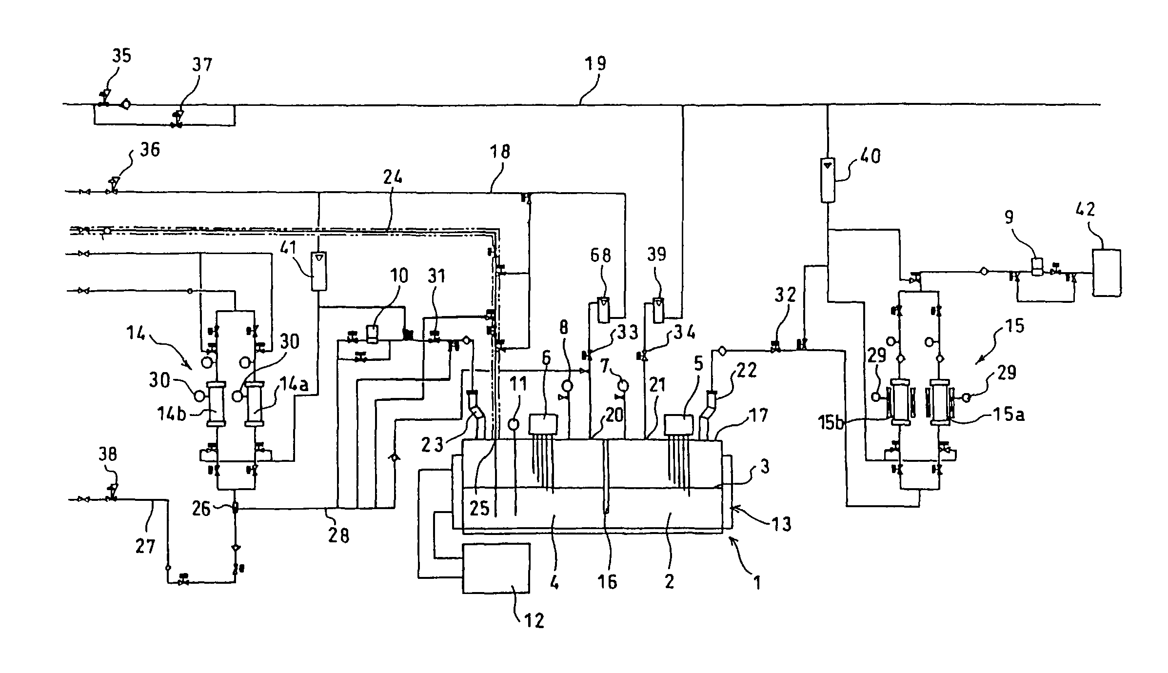
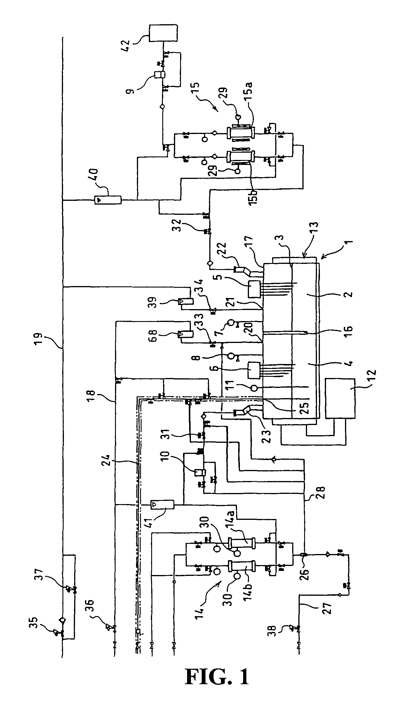
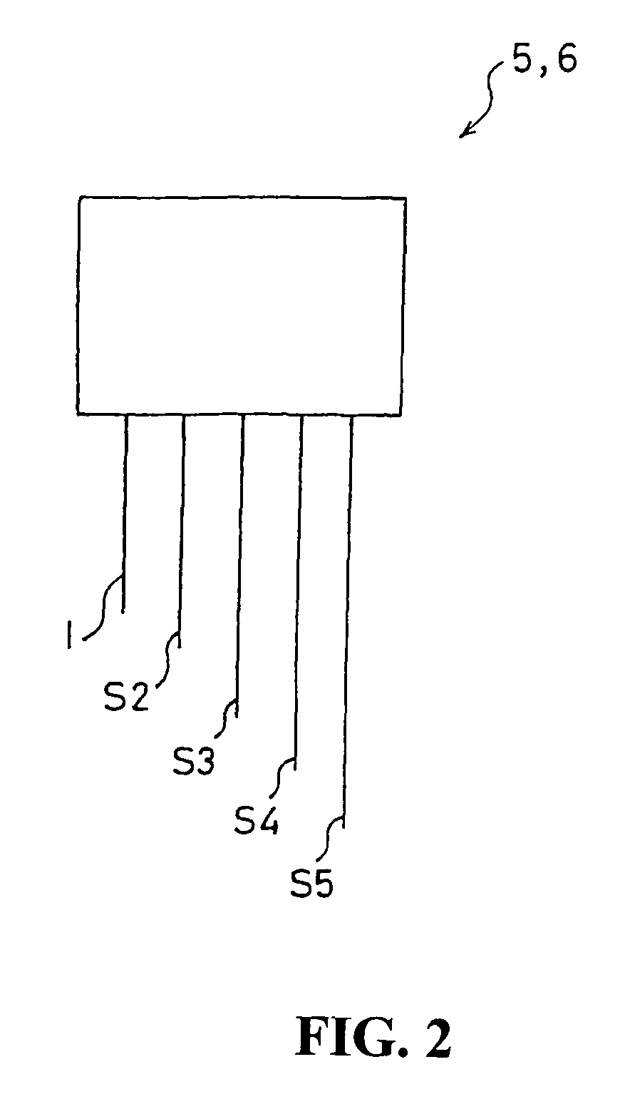
[0028]FIG. 1 is a schematic representation of the principal part of a fluorine gas generator according to the invention. In FIG. 1, 1 is an electrolytic cell, 2 is an electrolytic bath consisting of a fused or molten KF-HF system-based salt, 3 is an anode chamber, 4 is a cathode chamber, 5 is first level sensing means for sensing the level of the electrolytic bath 2 in the anode chamber 3, 6 is second level sensing means for sensing the liquid level in the cathode chamber 4 at 5 level stages. Further, 7 is a pressure gauge for measuring the pressure in the anode chamber, and 8 is a pressure gauge for measuring the pressure in the cathode chamber 4. 9 and 10 are automatic valves operated in association with the pressures measured by the pressure gauges 7 and 8. 11 is a thermometer for measuring the temperature of the electrolytic bath 2, and 12 is temperature control...


PUM

PropertyMeasurementUnit
Pressureaaaaaaaaaa
Levelaaaaaaaaaa

Abstract

A fluorine gas generator for generating highly pure fluorine gas in a stable and safe manner by electrolyzing an electrolytic bath 2 comprising hydrogen fluoride in the form of a molten mixed gas is provided which comprises an electrolytic cell 1 divided, by a partition wall 16, into an anode chamber 3 in which an anode is disposed and a cathode chamber 4 in which a cathode is disposed, pressure maintenance means for maintaining the anode chamber 3 and cathode chamber 4 at atmospheric pressure, and liquid level sensing means 5, 6 capable of sensing the levels of the electrolytic bath 2 in the anode chamber 3 and in the cathode chamber 4, respectively, at three or more level stages.

Description

BACKGROUND OF THE INVENTION[0001]1. Field of the Invention[0002]The present invention relates to an on-site type fluorine gas generator.[0003]2. Description of the Prior Art[0004]Fluorine gas is one of the key gases essential in the field of semiconductor production, for instance. While it is used as such in certain instances, the demand for nitrogen trifluoride gas (hereinafter referred to as “NF3 gas”) and like gases synthesized based on fluorine gas and intended for use as cleaning gases or dry etching gases in semiconductor manufacturing apparatus has been rapidly increasing. Further, neon fluoride gas (hereinafter referred to as “NeF gas”), argon fluoride gas (hereinafter referred to as “ArF gas”), krypton fluoride gas (hereinafter referred to as “KrF gas”) and the like are excimer laser oscillation gases used in patterning of integrated semiconductor circuits, and the raw materials thereof used in many cases are mixed gases composed of a rare gas and gaseous fluorine.[0005]The...

Claims


Application Information

Patent Timeline
IPC IPC(8): C25B9/00C25B1/24C25B15/02
CPCC25B15/02C25B1/245C25B15/00
Inventor TOJO, TETSUROHIRAIWA, JIROYOSHIMOTO, OSAMUTAKEBAYASHI, HITOSHITADA, YOSHITOMITANAKA, UDAI
Owner TOYO TANSO KK
Learn More