
Electrical connector

a technology of electrical connectors and connectors, applied in the direction of coupling device connections, coupling protective earth/shielding arrangements, electric discharge lamps, etc., can solve the problems of short circuit failure, conductive terminal portions are still prone to contact, short circuit may occur, etc., and achieve the effect of preventing short circuit failur

Inactive Publication Date: 2011-10-18
MOLEX INC
View PDF1 Cites 40 Cited by
  • Summary
  • Abstract
  • Description
  • Claims
  • Application Information

AI Technical Summary

Benefits of technology

[0009]In comparison with the prior art, the beneficial technical effects of the present invention lie in: by at least one positioning modules enveloping the bending portions between the butting portions and soldering portions of the conductive terminals to define the position relationship among the conductive terminals, the bending portions of the conductive terminals can be prevented from further bending and contacting with each other when an external force is applied and thus the short circuit failure can be prevented.
of the present invention lie in: by at least one positioning modules enveloping the bending portions between the butting portions and soldering portions of the conductive terminals to define the position relationship among the conductive terminals, the bending portions of the conductive terminals can be prevented from further bending and contacting with each other when an external force is applied and thus the short circuit failure can be prevented.

Problems solved by technology

As the electrical connector develops towards increasingly miniaturization, the conductive terminals in the electrical connector are designed to be more and more thin, and the spacing among the conductive terminals is more and more small, such that the conductive terminals are prone to contact with each other and the short circuit failure may occur when an external force is applied.
However, this positioning plate with positioning holes can only cover the soldering portions of the conductive terminals which extend downwards vertically, and the bending portions extending between an butting portions and the soldering portions of the conductive terminals are still exposed at the outside of the positioning plate and can not be fixed in position.
As a result, in case of assembly or application of an external force, the bending portions of the conductive terminals are still prone to contact with each other, and the short circuit may occur.

Method used


Image

  • Electrical connector
  • Electrical connector
  • Electrical connector

Examples


Embodiment Construction

[0024]The present invention will be described in detail with reference to the drawings, by taking the Mini-Displayport electrical connector as an example.

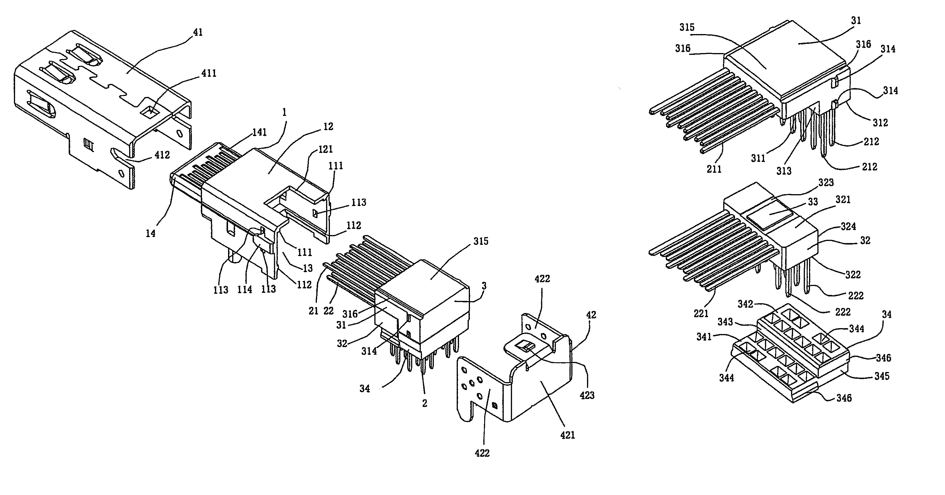
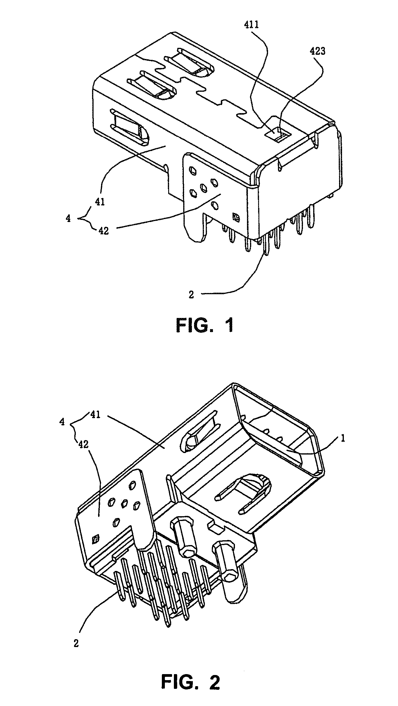
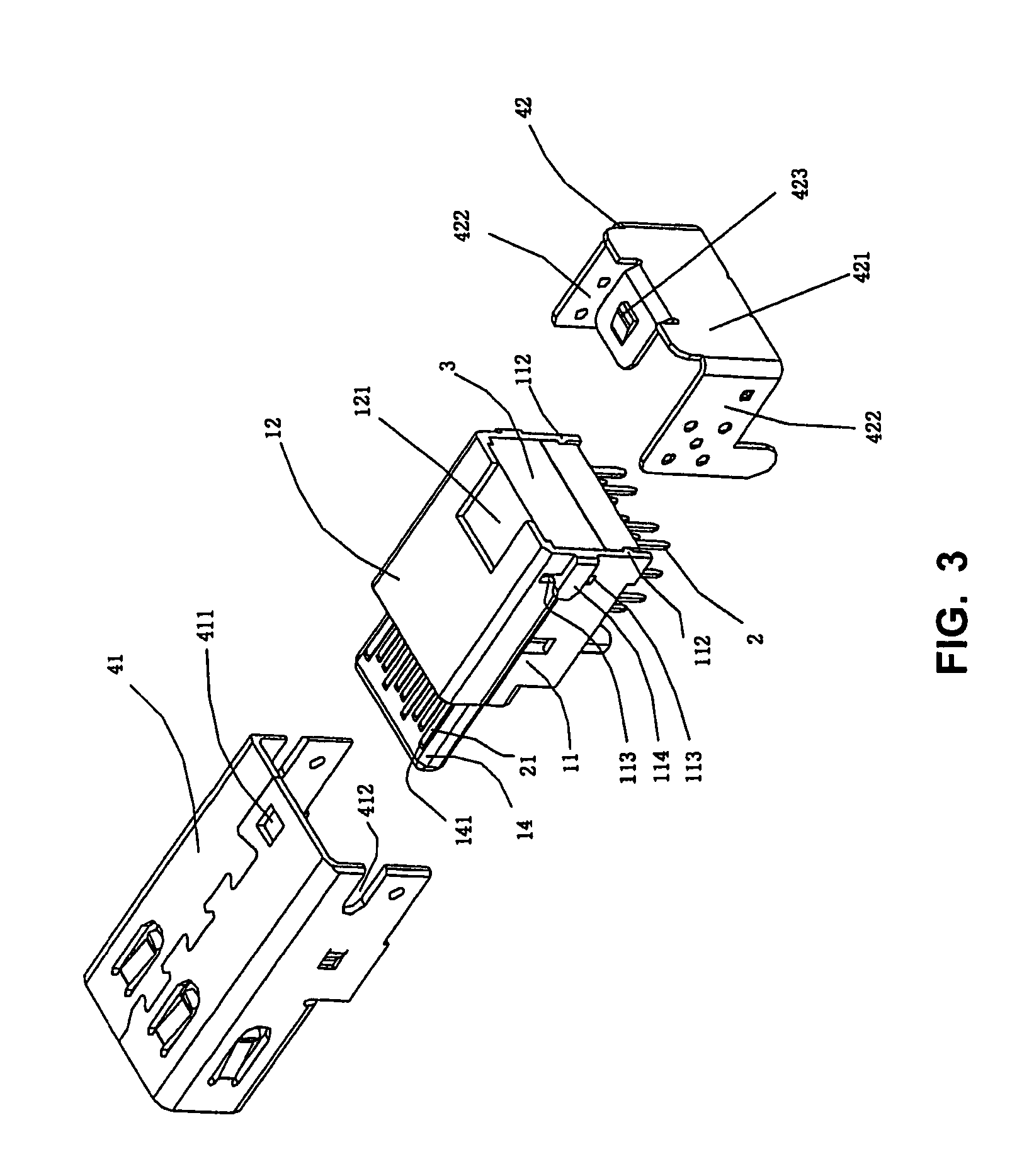
[0025]As shown in FIGS. 1 to 4, an electrical connector according to a preferred embodiment of the present invention comprises an insulating housing 1, a plurality of conductive terminals 2 fitted on the insulating housing 1, a positioning module 3 for fixing the plurality of conductive terminals 2, a spacer plate 34, and a shielding casing 4.

[0026]Referring to FIGS. 5 and 6, an accommodating chamber 13 is provided at the rear portion of the insulating housing, which is formed by two sidewalls 11 and a top wall 12, and a tongue plate 14 is protruded forwards from the front portion of the insulating housing 1. A plurality of terminal receiving grooves 141 are provided at both of the upper and lower sides of the tongue plate 14, which penetrate through the insulating housing 1 from front to rear. Both of the inner surfaces of two sid...


PUM


Abstract

An electrical connector comprises: an insulating housing having an accommodating chamber at a rear portion thereof and a tongue plate protruding forwards from a front portion thereof; a plurality of conductive terminals comprising an upper row of conductive terminals and a lower row of conductive terminals which are mounted on upper and lower sides of the tongue plate respectively, each conductive terminal including a butting portion, a soldering portion, and a bending portion connected between the butting portion and the soldering portion, the butting portions of said upper row of conductive terminals and lower row of conductive terminals being mounted on the upper and lower sides of the tongue plate respectively, the soldering portions of each row of conductive terminals extending from below the rear portion of the insulating housing and being arranged in a front column and a rear column; a shielding casing covering periphery of the insulating housing; and two positioning modules being mounted into the accommodating chamber of the insulating housing and enveloping periphery of the bending portions of said plurality of conductive terminals. The electrical connector can efficiently prevent bending portions of the conductive terminals from further bending and contacting with each other when an external force is applied and thus can prevent the short circuit failure.

Description

BACKGROUND OF THE INVENTION[0001]This application claims priority to Chinese Application No. 200920001857.X, filed Jan. 22, 2009, which is incorporated herein by reference in its entirety.TECHNICAL FIELD[0002]The present invention relates to an electrical connector, in particular to an electrical connector which can prevent short circuit of conductive terminals due to contact with each other.BACKGROUND ART[0003]As the electrical connector develops towards increasingly miniaturization, the conductive terminals in the electrical connector are designed to be more and more thin, and the spacing among the conductive terminals is more and more small, such that the conductive terminals are prone to contact with each other and the short circuit failure may occur when an external force is applied.[0004]To efficiently prevent the short circuit between the conductive terminals due to contact with each other, Chinese Patent ZL 200720042398.0 disclosed an electrical connector, which generally co...

Claims


Application Information

Patent Timeline
Patent Type & Authority Patents(United States)
IPC IPC(8): H01R24/00
CPCH01R13/502H01R12/724H01R43/24
Inventor WEI, KE CHANG
Owner MOLEX INC
Learn More