Thread forming fasteners for ultrasonic load measurement and control

a technology of ultrasonic load measurement and control, applied in the direction of screws, instruments, force/torque/work measurement apparatus, etc., can solve the problems of 3 sigma load scatter of typically +/50%, the general restriction of thread-forming fasteners to non-critical or less-critical applications, and the difficulty in controlling the tightening process to prevent their use in critical applications. , to achieve the effect of accurate measurement and control of load in the thread-forming fastener

Inactive Publication Date: 2011-10-18
INNOVATION PLUS LLC
View PDF99 Cites 3 Cited by
  • Summary
  • Abstract
  • Description
  • Claims
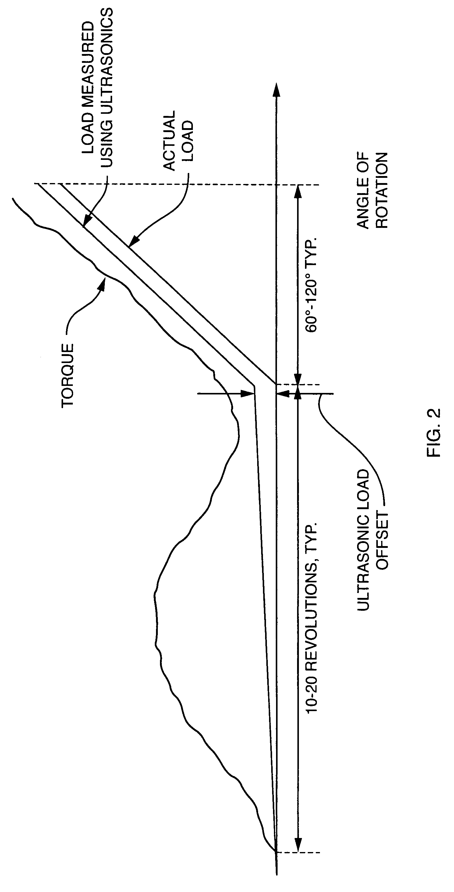
  • Application Information

AI Technical Summary

Benefits of technology

[0008]In accordance with the present invention, it has been determined that such ultrasonics can be mated with an otherwise conventional thread-forming fastener to provide a load indicating thread-forming fastener that can be used for precise and reliable assembly of critical bolted joints, such as those in automobile engines (e.g., cylinder heads, connecting rods, main bearings, etc.), drive trains, steering, brakes, suspensions, and a variety of other applications, including aerospace applications.
[0009]Steps can then be taken, using equipment and methods that are otherwise known and conventional, to accurately measure and control the load in the thread-forming fastener during tightening, and to inspect the load in the thread-forming fastener after assembly.

Problems solved by technology

Although thread-forming fasteners have been used in numerous applications in the automotive and aerospace industries to reduce cost, such fasteners are generally restricted to non-critical or less-critical applications.
The difficulty in controlling the tightening process prevents their use in critical applications.
As a result, the precise tightening of a thread-forming fastener to a specified torque into a blind hole, where the thread is still being formed as the bolt is being tightened, will result in a 3 sigma load scatter of typically + / −50%, which is unacceptable in critical applications.

Method used


Image

  • Thread forming fasteners for ultrasonic load measurement and control
  • Thread forming fasteners for ultrasonic load measurement and control
  • Thread forming fasteners for ultrasonic load measurement and control

Examples


Embodiment Construction

[0013]FIG. 1 shows a typical embodiment of a load indicating thread-forming fastener which is produced in accordance with the present invention. In this illustrative example, the load indicating thread-forming fastener has been implemented in conjunction with an otherwise conventional “Taptite” fastener, which is commercially available from Reminc, Research Engineering and Manufacturing Inc., Middletown, R.I., USA. It is to be understood, however, that this embodiment is shown only for purposes of illustration, and that the load indicating thread-forming fastener of the present invention can also be implemented using any of a variety of known and available load indicating devices, coupled or combined with any of a variety of known and available thread-forming fasteners.

[0014]In the illustrative embodiment of FIG. 1, the load indicating thread-forming fastener 10 generally includes a fastener 12 (e.g., the above-mentioned “Taptite” fastener) and a permanent piezoelectric polymer film...


PUM

PropertyMeasurementUnit
ultrasonic load measurementsaaaaaaaaaa
torqueaaaaaaaaaa
ultrasonic loadaaaaaaaaaa

Abstract

An ultrasonic load measurement transducer (14) is mated with a thread-forming fastener (12) to provide a load indicating thread-forming fastener (10) that can be used for precise and reliable assembly of critical bolted joints, such as those in the automobile and aerospace industries, among others. Steps can then be taken to accurately measure and control the load in the thread-forming fastener (10) during tightening, and to inspect the load in the thread-forming fastener (10) after assembly. A similar result can be achieved for a thread-locking fastener by mating an ultrasonic transducer with the thread-locking fastener assembly.

Description

CROSS-REFERENCE TO RELATED APPLICATIONS[0001]This application claims the benefit of U.S. Provisional Application No. 60 / 412,125, filed Sep. 19, 2002. This application is also a continuation-in-part of U.S. patent application Ser. No. 10 / 470,372, which has an assigned filing date of Jul. 25, 2003, which was the National Stage of International Application No. PCT / US02 / 03920, filed Jan. 28, 2002, and which claims the benefit of U.S. Provisional Application No. 60 / 264,877, filed Jan. 29, 2001.BACKGROUND OF THE INVENTION[0002]This invention relates to load indicating fasteners that are “thread-forming” (also referred to as “thread-rolling” or “self-tapping” fasteners), methods for making load indicating thread-forming fasteners, and methods for measuring the load in thread-forming fasteners.[0003]Thread-forming fasteners are well known in many industries, such as in high-volume automotive assembly. Examples of such fasteners are described in U.S. Pat. No. 5,242,253 (Fulmer), issued Sep. ...

Claims


Application Information

Patent Timeline
Patent Type & Authority Patents(United States)
IPC IPC(8): F16B31/02F16BF16B25/00G01L5/24
CPCF16B31/02G01L5/246F16B2031/022
Inventor KIBBLEWHITE, IAN E.MOLSBERGEN, ROBERT
Owner INNOVATION PLUS LLC
Why Eureka
Try Eureka