Method for influencing soot deposits on sensors

a technology of sensors and soot, applied in the direction of instruments, suspensions, resistance/reactance/impedence, etc., to achieve the effect of enhancing the system's reliability

Active Publication Date: 2011-10-11
ROBERT BOSCH GMBH
View PDF13 Cites 20 Cited by
  • Summary
  • Abstract
  • Description
  • Claims
  • Application Information

AI Technical Summary

Benefits of technology

[0007]The sensor situated upstream from the diesel particle filter system is used for enhancing the system's reliability and for ensuring operation of the diesel particle filter under optimum conditions. Since those factors depend, to a considerable extent, on the soot mass deposited in the diesel particle filter, accurate measurement of the particle concentration upstream from the diesel particle filter, in particular ascertaining a high particle concentration upstream from the diesel particle filter, is very important.

Problems solved by technology

Since the soot concentrations upstream and downstream from the diesel particle filter may differ considerably depending on the technology used, however, cost considerations make identical sensors desirable.

Method used


Image

  • Method for influencing soot deposits on sensors
  • Method for influencing soot deposits on sensors
  • Method for influencing soot deposits on sensors

Examples


Embodiment Construction

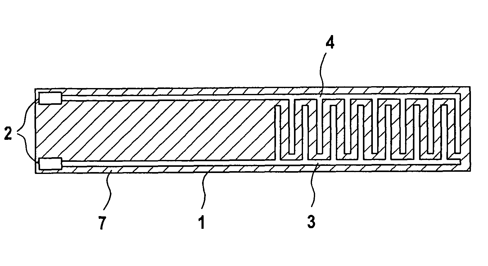
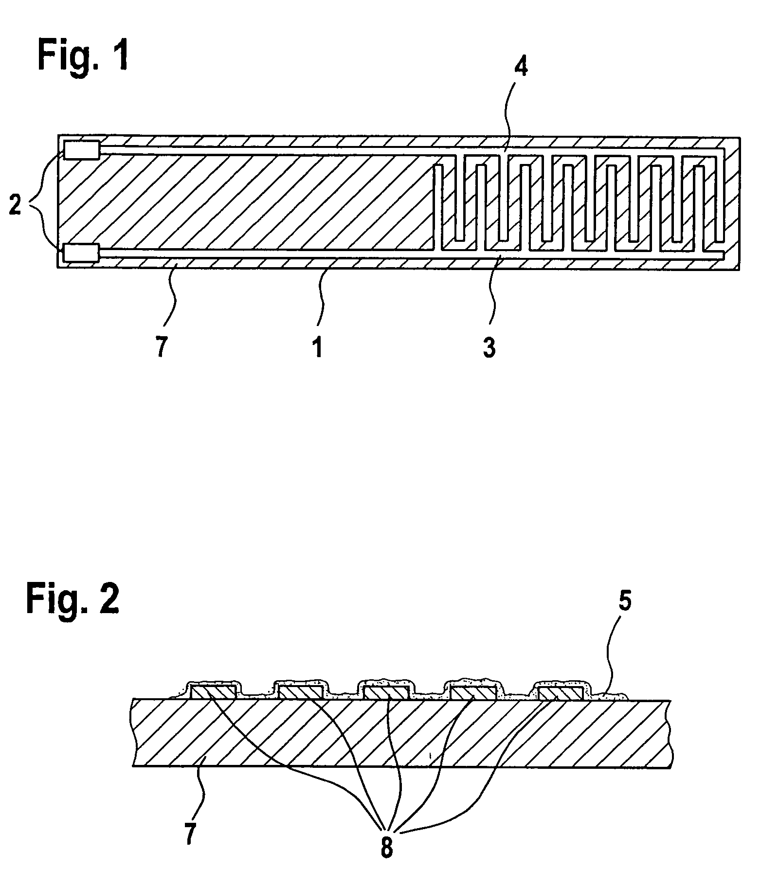
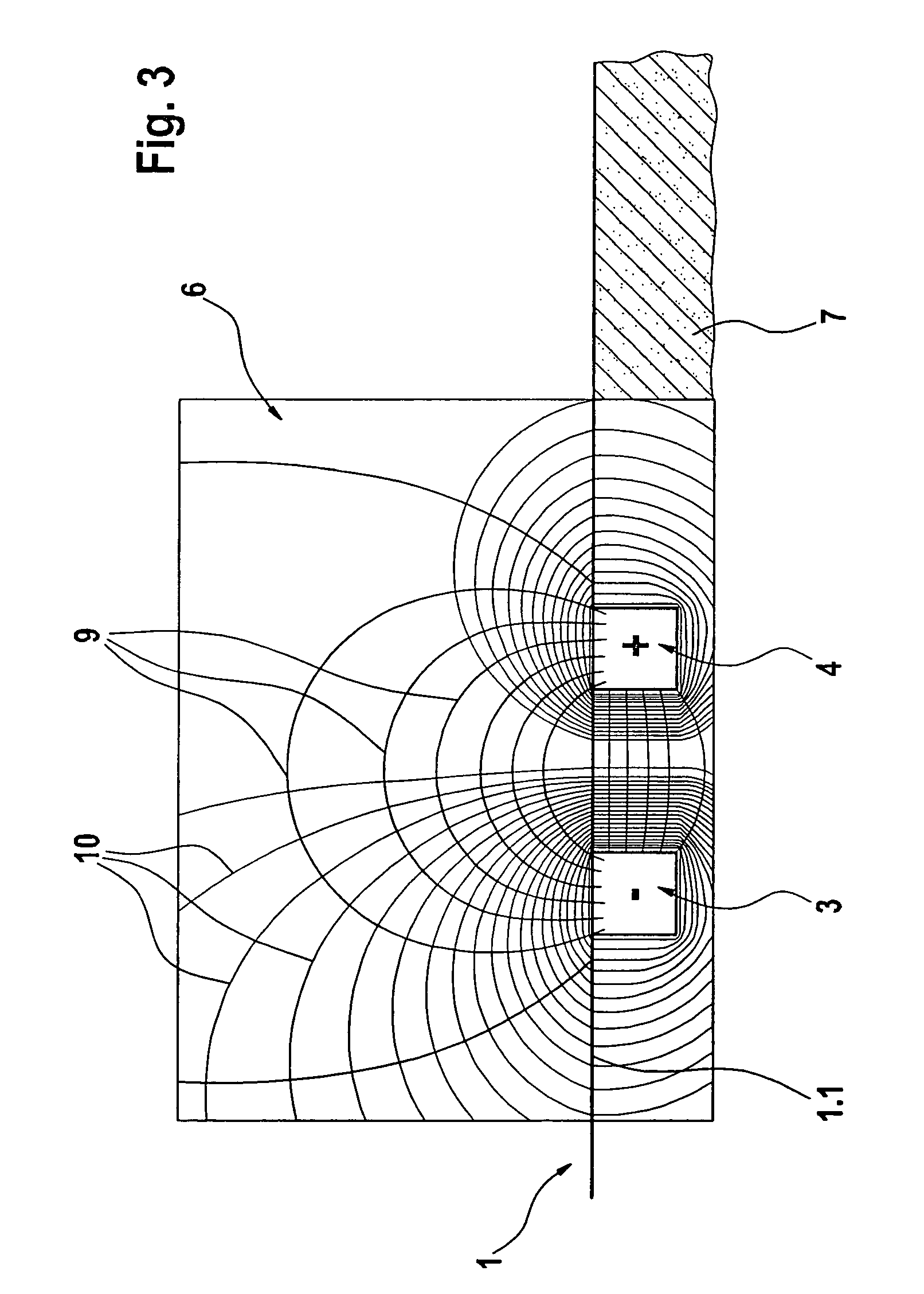
[0015]Sensor element 1 includes a substrate 7 used as a support, which may be made of an aluminum oxide ceramic, for example. A resistance measuring structure, having a first comb electrode 3 and a second comb electrode 4, is applied to substrate 7 used as support. The resistance measuring structure including first comb electrode 3 and second comb electrode 4 is used for measuring the electric resistance of a particle layer 5—see the illustration of FIG. 2, which covers first comb electrode 3 and second comb electrode 4 of sensor element 1. When a voltage is applied to voltage terminals 2 of sensor element 1, an inhomogeneous electric field 6 is formed between meshing comb electrodes 3, 4, see the illustration of FIG. 3, where the inhomogeneous electric field 6 is represented by field lines 9.

[0016]The particles, in particular soot particles, depositing on sensor element 1 may be considered electric dipoles in the electric field. Inhomogeneous electric field 6 exerts a resulting for...


PUM

PropertyMeasurementUnit
voltageaaaaaaaaaa
voltageaaaaaaaaaa
voltageaaaaaaaaaa

Abstract

A method is described for controlling the soot deposition on sensors. A sensor element is provided, which includes a first electrode and a second electrode. Different measuring voltages U1 and U2 can be applied to the sensor element. During a first time period t1, the sensor element is operated at a higher voltage U1 until a triggering threshold AP of the sensor element is exceeded, while it is operated at a voltage U2, which is different from higher voltage U1, U2 being lower than voltage U1, during a second time period t2.

Description

BACKGROUND INFORMATION[0001]Particle emission requirements for internal combustion engines, in particular compression-ignition internal combustion engines, are becoming increasingly stricter. As the introduction of further standards is being planned, the soot emissions downstream from the internal combustion engine, i.e., downstream from a diesel particle filter, must be monitored during the driving operation. In addition, prediction of the diesel particle filter load is to be provided for determining the soot input and optimizing the regeneration strategy or monitoring regeneration in order to ensure a high degree of system reliability for the diesel particle filter system.[0002]Currently, resistive particle sensors for conductive particles are known in which two or more metallic electrodes are provided, the particles, in particular soot particles, which deposit on these sensors short-circuiting the electrodes meshing in a comb-like manner and thus modifying the impedance of the el...

Claims


Application Information

Patent Timeline
Patent Type & Authority Patents(United States)
IPC IPC(8): G01R27/08G01N37/00G01N27/00G01N15/06
CPCG01N15/0656
Inventor SCHNELL, FRANKDORFMUELLER, LUTZSCHMIDT, RALFROESCH, SABINEMARX, HELMUTSCHITTENHELM, HENRIK
Owner ROBERT BOSCH GMBH
Why Eureka
Try Eureka