
Current source converter-based wind energy system

a technology of wind energy system and converter, applied in the direction of motor/generator/converter stopper, electric generator control, dynamo-electric converter control, etc., to achieve the effect of discharging excess power in fault mod

Inactive Publication Date: 2011-10-04
ROCKWELL AUTOMATION TECH
View PDF26 Cites 77 Cited by
  • Summary
  • Abstract
  • Description
  • Claims
  • Application Information

AI Technical Summary

Benefits of technology

This solution enables effective reactive power control and grid fault tolerance, allowing wind energy systems to adapt to grid conditions and provide stable electrical power to the grid while minimizing the need for large filter capacitors.

Problems solved by technology

Conventional wind energy systems (WES) typically do not employ current source converters, due to the difficulties in controlling output reactive power to the grid, as the CSC systems require large filter capacitors at the output and hence usually has a leading power factor, particularly during low speed operation.

Method used


Image

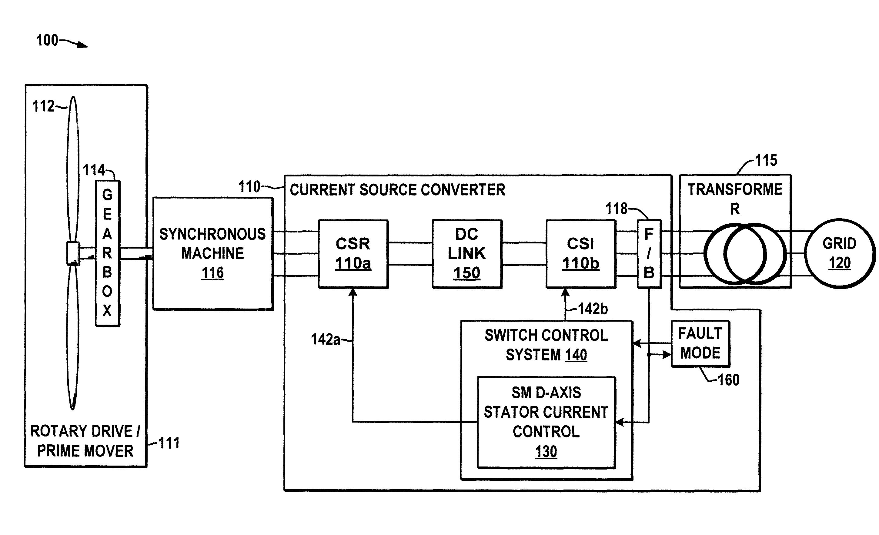
  • Current source converter-based wind energy system
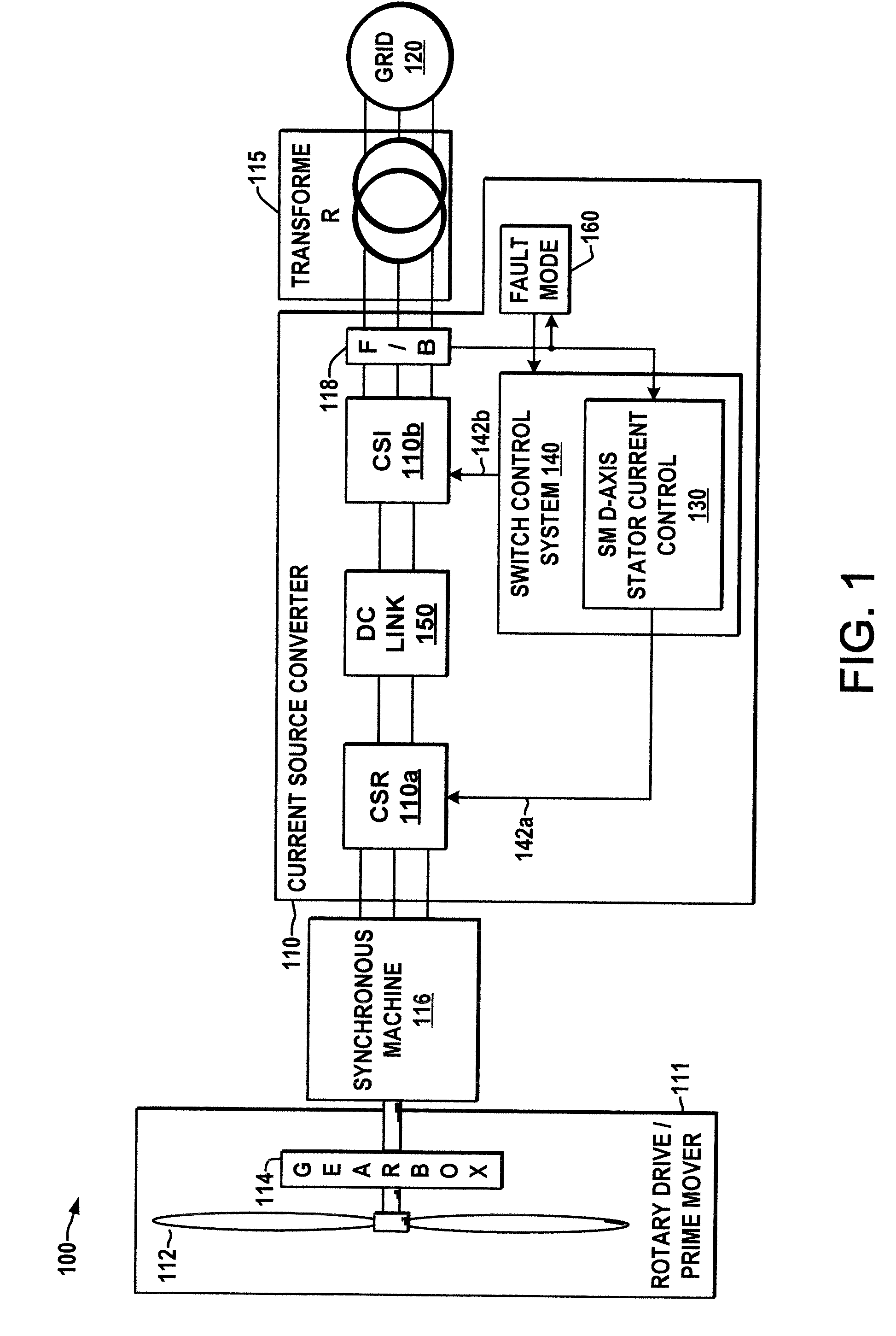
  • Current source converter-based wind energy system
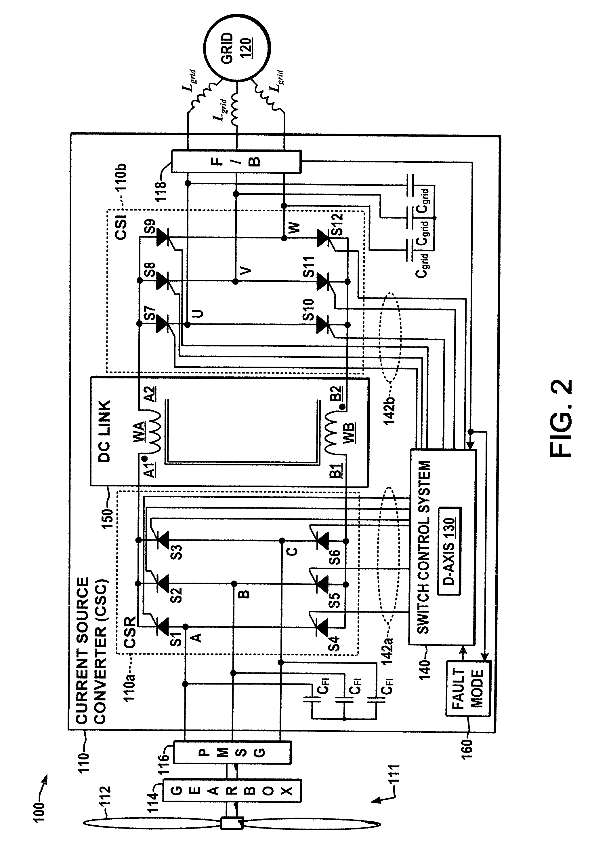
  • Current source converter-based wind energy system

Examples


Embodiment Construction

[0024]Referring now to the figures, several embodiments or implementations of the present invention are hereinafter described in conjunction with the drawings, wherein like reference numerals are used to refer to like elements throughout, and wherein the various features are not necessarily drawn to scale.

[0025]FIGS. 1 and 2 illustrate an exemplary wind energy converter (WEC) or wind energy system (WES) 100 in accordance with the present disclosure, in which a current source converter (CSC) 110 is connected to an AC power source derived from a wind-receiving rotary propeller 112 operatively coupled with a synchronous machine, in one example, a permanent magnet synchronous generator (PMSG) 116 operating in this case as a generator with a permanent magnet rotor. The system 100 may optionally include a gearbox 114 operatively coupled between the propeller 112 and the PMSG 116, although not a strict requirement of the present disclosure. The PMSG 116 converts rotational mechanical energ...


PUM


Abstract

Power conversion apparatus and methods are presented for providing electrical power to a grid or other load in which a synchronous machine is driven by a wind turbine or other prime mover to provide generator power to a switching type current source converter (CSC), with a current source rectifier (CSR) of the CSC being switched to provide d-axis control of the synchronous machine current based on grid power factor feedback, and with a current source inverter (CSI) of the CSC being switched to provide leading firing angle control and selective employment of dumping resists to dissipate excess generator energy in a fault mode when a grid voltage drops below a predetermined level.

Description

FIELD OF THE INVENTION[0001]The present invention relates generally to electrical power conversion and more particularly to current source converter-based wind energy systems.BACKGROUND OF THE INVENTION[0002]Wind energy is currently a fast growing power generation technology, and ongoing development is directed to providing wind-generated power to electrical power grids. Power conversion systems are needed to adapt the power generated by the wind turbines to AC electric power in a form compatible with the power grid. One type of conversion apparatus is a current source converter (CSC) that includes a current source rectifier (CSR) and a current source inverter (CSI, also known as a current controlled inverter). Conventional wind energy systems (WES) typically do not employ current source converters, due to the difficulties in controlling output reactive power to the grid, as the CSC systems require large filter capacitors at the output and hence usually has a leading power factor, p...

Claims


Application Information

Patent Timeline
Patent Type & Authority Patents(United States)
IPC IPC(8): F03D9/00H02P9/04
CPCH02M5/4505H02P9/10H02P9/48H02J3/386H02P2101/15Y02E10/763H02P2201/13H02P21/00H02M1/32H02J2300/28H02J3/381Y02E10/76H02J3/44
Inventor LANG, YONGQIANGZARGARI, NAVID REZAPANDE, MANISHWU, BIN
Owner ROCKWELL AUTOMATION TECH
Learn More