
Method for setting gear tooth profile in flat wave gear device on side where gears have same number of teeth

a gear tooth and gear technology, applied in the field of flat wave gear devices, can solve the problems that no adequate investigation has yet been made into the tooth profile, and achieve the effects of accurate tooth profile design, zero backlash, and increased ratcheting torqu

Active Publication Date: 2011-10-04
HARMONIC DRIVE SYST IND CO LTD
View PDF15 Cites 23 Cited by
  • Summary
  • Abstract
  • Description
  • Claims
  • Application Information

AI Technical Summary

Benefits of technology

The present invention relates to a flat wave gear device with a flexible externally toothed gear and a rigid internally toothed gear, and a method for setting a tooth profile in the rigid internally toothed gear. The invention aims to accurately determine the movement locus of teeth in the flexible externally toothed gear and the tooth profile of the rigid internally toothed gear, and to use this information to design a gear system with improved performance. The method involves determining the contact point between the flexible externally toothed gear and the rigid internally toothed gear, and using this information to calculate the tooth profile of the rigid internally toothed gear. The invention provides a more accurate understanding of the gear system's movement and tooth profile, which can lead to improved performance and efficiency of the gear device.

Problems solved by technology

Particularly in the latter case, no adequate investigations have yet to be made into a tooth profile that accounts for the actual number of teeth.

Method used


Image

  • Method for setting gear tooth profile in flat wave gear device on side where gears have same number of teeth
  • Method for setting gear tooth profile in flat wave gear device on side where gears have same number of teeth
  • Method for setting gear tooth profile in flat wave gear device on side where gears have same number of teeth

Examples


Embodiment Construction

[0036]A method for setting a tooth profile in a flat wave gear device in which the present invention is used will be described below with reference to the attached drawings.

[0037](Configuration of Flat Wave Gear Device)

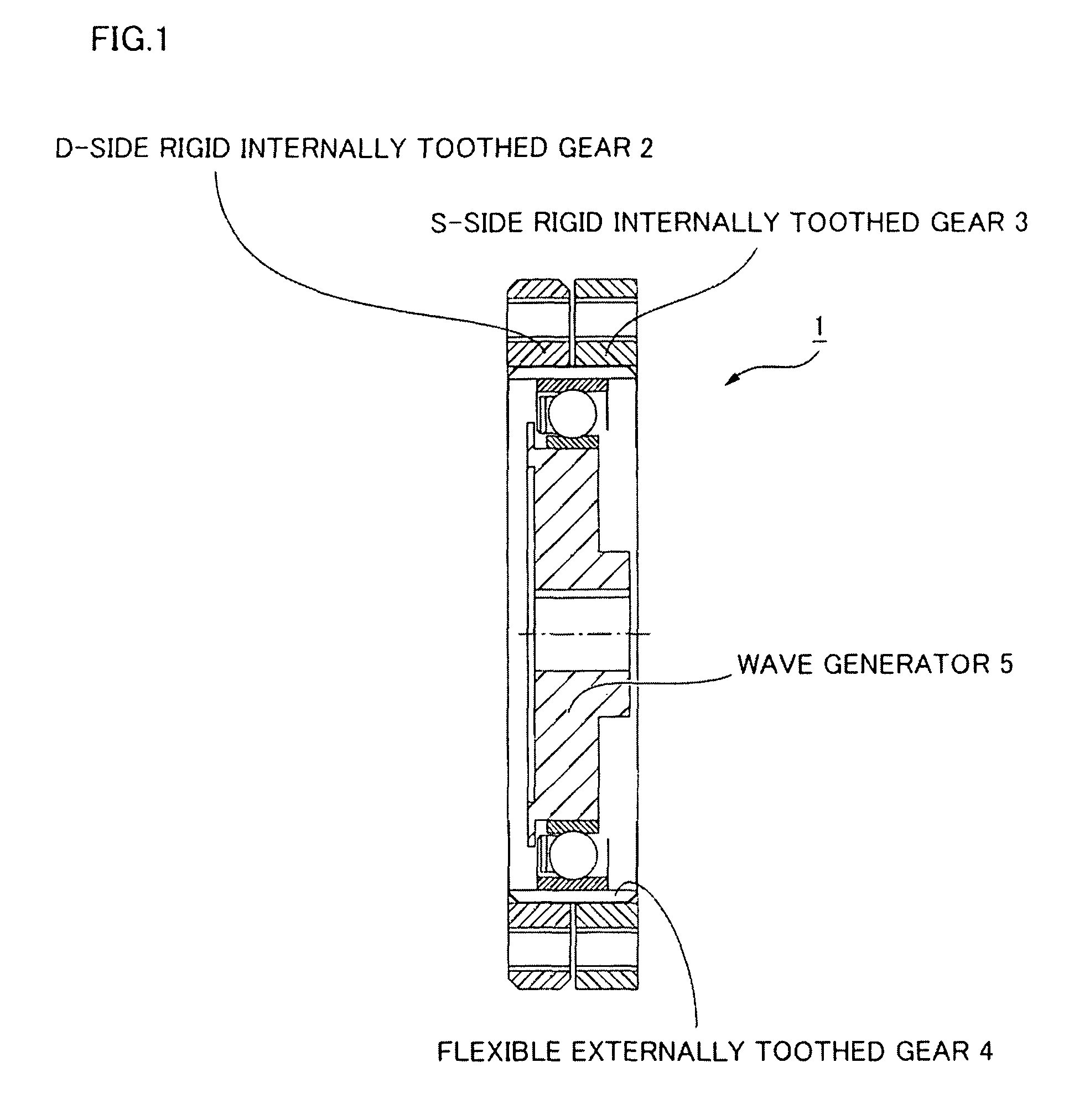
[0038]FIG. 1 is a sectional diagram showing a flat wave gear device in which the present invention can be used. A flat wave gear device 1 has two rigid internally toothed gears 2, 3 disposed in parallel in a coaxial state, an annular flexible externally toothed gear 4 disposed in a coaxial state within the two rigid internally toothed gears, and a wave generator 5 having an elliptical outline fitted within the flexible externally toothed gear. The rigid internally toothed gear 2 has the same number of teeth as the flexible externally toothed gear 4, but the rigid internally toothed gear 3 has 2n more teeth than the flexible externally toothed gear 4 (n being a positive integer). When the elliptically contoured wave generator 5 is caused to rotate, counter-rotation occ...


PUM


Abstract

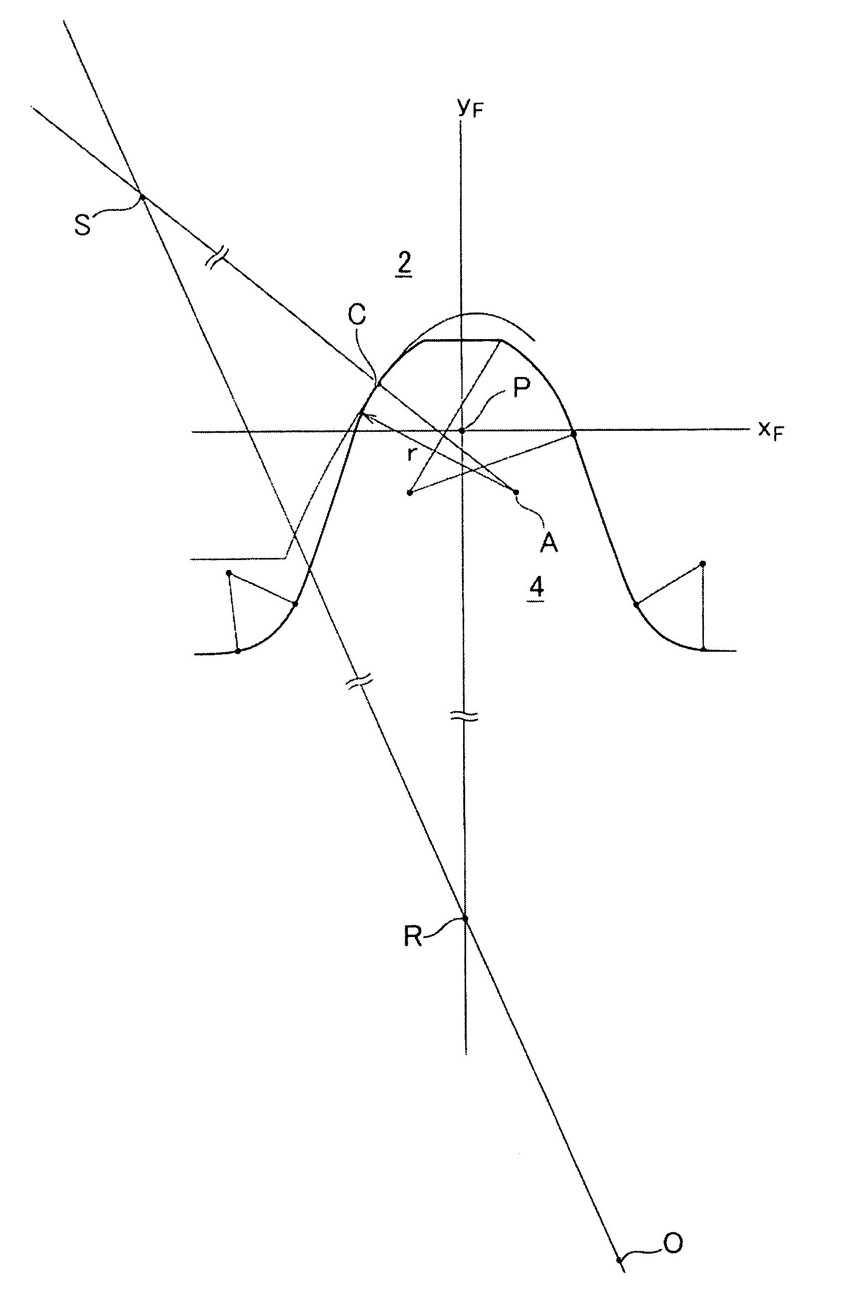
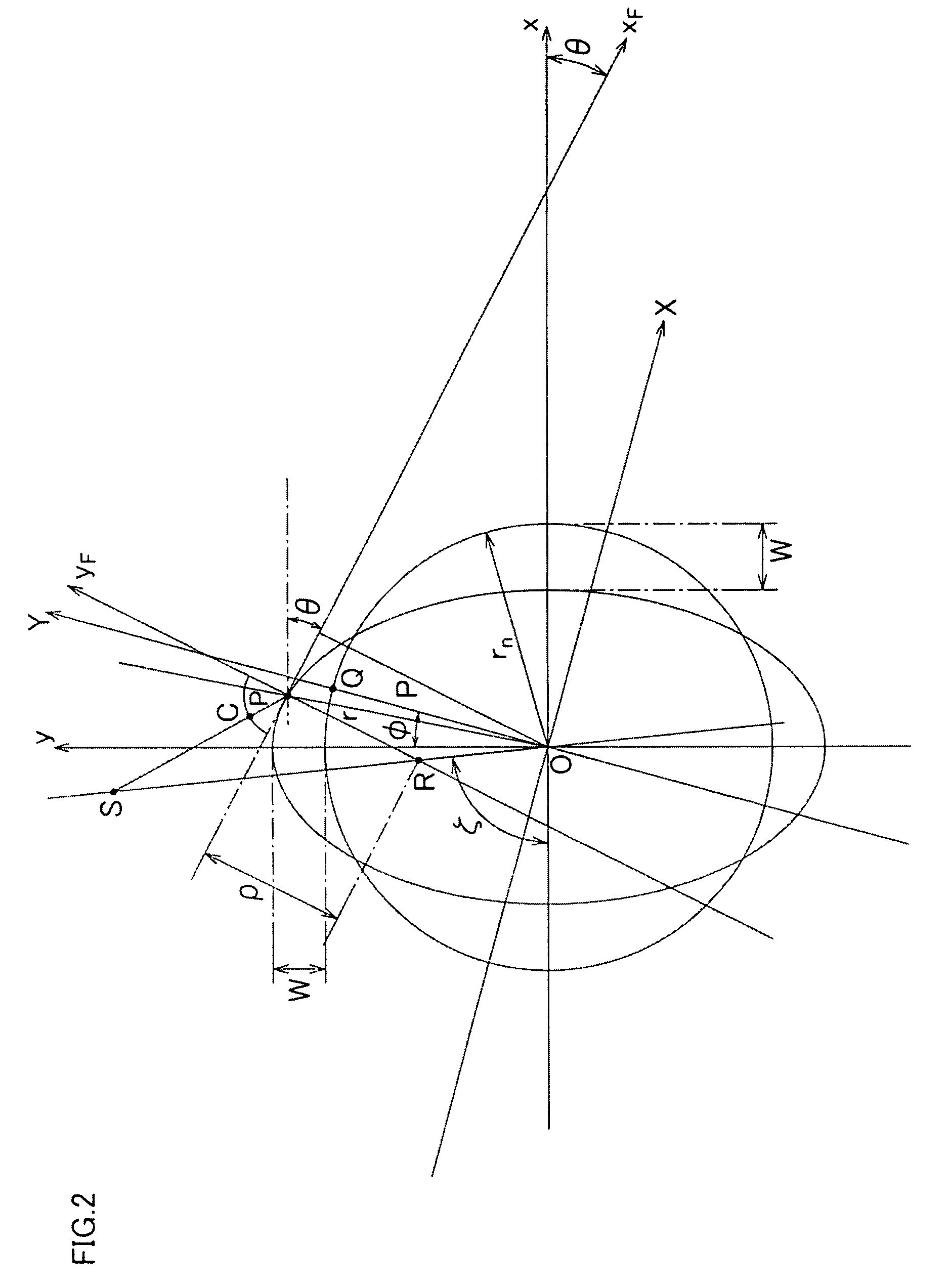
In a flat wave gear device in which a flexible externally toothed gear and the rigid internally toothed gear have the same number of teeth, an arcuate tooth profile is imparted to a flexible externally toothed gear, a contact point C between tooth profiles of a flexible externally toothed gear and a D-side rigid internally toothed gear is determined from an arc center A of the arcuate tooth profile of the flexible externally toothed gear and from a momentary center S of relative movement between the gears, and a main part of a tooth profile to be formed in the D-side rigid internally toothed gear is calculated based on the contact point. The tooth profile of the D-side rigid internally toothed gear can be accurately designed; therefore, meshing between the gears can occur with zero backlash, ratcheting torque can be increased, and continuous meshing can occur across a wide range of the movement locus of the tooth profiles of both gears. The load capability of the flat wave gear device can accordingly be increased.

Description

TECHNICAL FIELD[0001]The present invention relates to a flat wave gear device, and in particular relates to a method for setting a tooth profile of a flexible externally toothed gear and a rigid internally toothed gear that have the same number of teeth, so that a high ratcheting torque is obtained as accurate meshing is achieved with zero backlash.BACKGROUND ART[0002]A wave gear device is provided with a rigid internally toothed gear, a flexible externally toothed gear, and a wave generator; the wave generator typically having an elliptical outline. The wave generator causes the flexible externally toothed gear to flex into an elliptical shape, and both ends along the major axis of the elliptical shape mesh with the rigid internally toothed gear. The number of teeth of the flexible externally toothed gear is 2n less (n is a positive number) than the number of teeth in the rigid internally toothed gear. When the wave generator is caused to rotate via a motor or the like, the positio...

Claims


Application Information

Patent Timeline
Patent Type & Authority Patents(United States)
IPC IPC(8): F16H33/00
CPCF16H55/0833G01B5/202Y10T74/19972Y10T74/19967Y10T74/19
Inventor ISHIKAWA, SHOICHI
Owner HARMONIC DRIVE SYST IND CO LTD
Learn More