Card edge connector

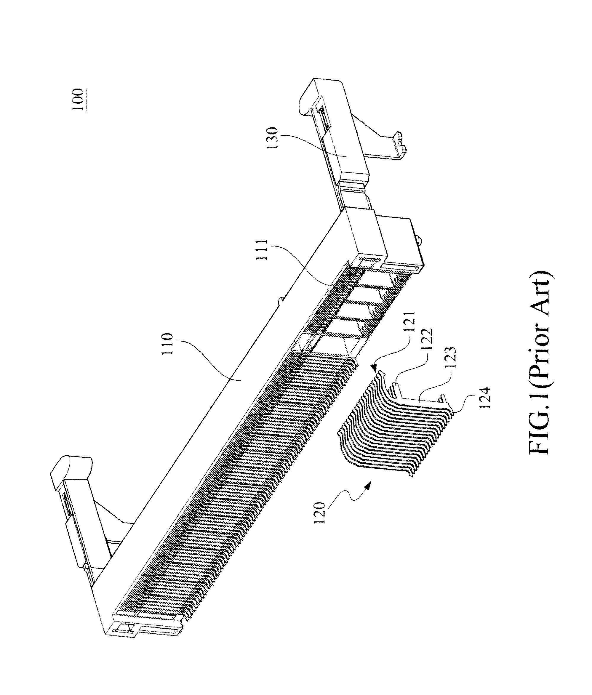
a card edge and connector technology, applied in the direction of coupling device connection, coupling/disengagement of coupling parts, electrical apparatus, etc., can solve the problem that the metal lead b>120/b> doesn't provide sufficient elasticity to protect against accidental mishaps, and achieve the effect of sufficient elasticity

Inactive Publication Date: 2011-09-20
CONCRAFT HLDG
View PDF8 Cites 7 Cited by
  • Summary
  • Abstract
  • Description
  • Claims
  • Application Information

AI Technical Summary

Benefits of technology

[0010]Accordingly, it is an object of the present invention to provide a card edge connector, which applies an insert-molded process to mount the terminals to a respective assembly part. Then, the assembly part is sent to be integrated with an insulation body. In addition, the present invention also provides the terminals sufficient elasticity so as to ensure the yield of pairing terminals.

Problems solved by technology

It is noted that the aforesaid metal lead 120 doesn't provide sufficient elasticity to act against an accidental mis-planting.

Method used


Image

  • Card edge connector
  • Card edge connector
  • Card edge connector

Examples


Embodiment Construction

[0029]The invention disclosed herein is directed to a card edge connector. In the following description, numerous details are set forth in order to provide a thorough understanding of the present invention. It will be appreciated by one skilled in the art that variations of these specific details are possible while still achieving the results of the present invention. In other instance, well-known components are not described in detail in order not to unnecessarily obscure the present invention.

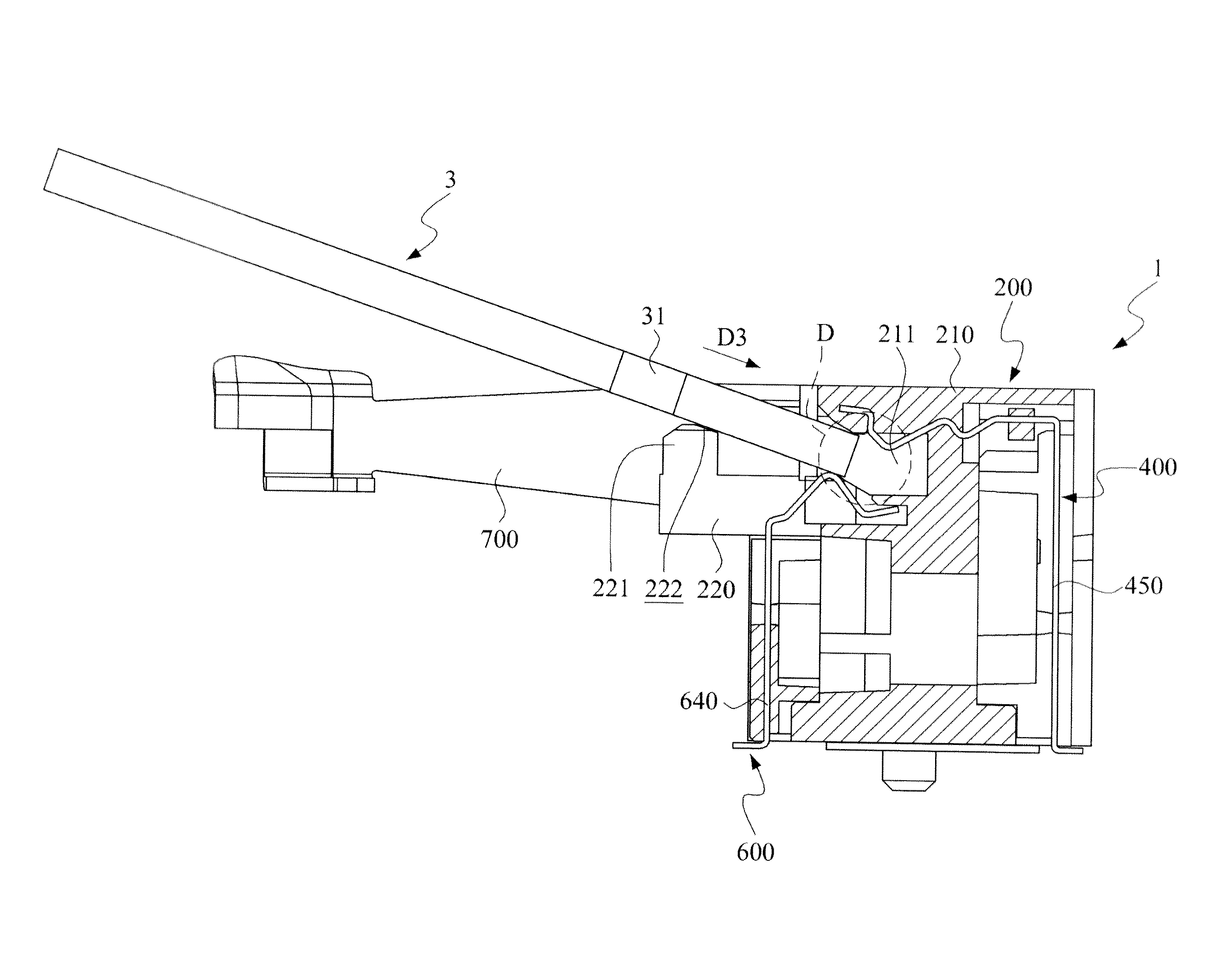
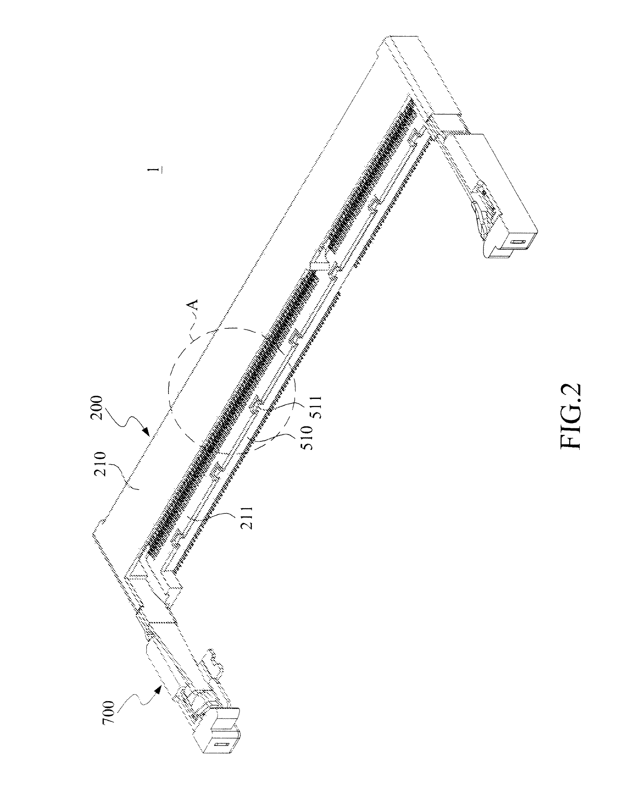
[0030]Referring now to FIG. 2, FIG. 3 and FIG. 4, a first (preferred) embodiment of the card edge connector in accordance with the present invention is shown in various views. The card edge connector 1 includes an insulation body 200, a first assembly part 300, a plurality of first terminals (metal leads) 400, a second assembly part 500, a plurality of second terminals 600 and two clamp arms 700. The insulation body 200 has a pair of receiving slots located on and extended along a front side ...


PUM


Abstract

A card edge connector includes an insulation body, a first assembly part, a second assembly part, a plurality of first terminals and a plurality of second terminals. The first terminals and the second terminals are respectively mounted into the first assembly part and the second assembly part. The first assembly part is assembled to the rear side of the insulation body, while the second assembly part is assembled to the lower side of the insulation body.

Description

[0001]This application claims the benefit of Taiwan Patent Application Serial No. 099212305, filed Jun. 29, 2010, the subject matter of which is incorporated herein by reference.BACKGROUND OF THE INVENTION[0002](1) Field of the Invention[0003]The invention relates to a card edge connector, more particularly to an assembly-type card edge connector.[0004](2) Description of the Prior Art[0005]It is usually to see variety connectors built inside to a housing of an electronic device such as a computer, a TV screen or any the like, to act as signal connection with respective foreign peripheral apparatuses.[0006]Referring to FIG. 1, a typical card edge connector of aforesaid connectors is perspective shown. The connector 100 includes an insulation body 110, a plurality of metal leads 120, and two support arms 130 oppositely located to respective sides of the insulation body 110. The insulation body 110 is a one-piece plastic part having a plurality of insert holes 110. Each of the metal le...

Claims


Application Information

Patent Timeline
Patent Type & Authority Patents(United States)
IPC IPC(8): H01R4/38
CPCH01R12/721H01R13/504
Inventor LEE, KUO-CHILIN, CHIN-HUANG
Owner CONCRAFT HLDG
Why Eureka
Try Eureka