
Method of fastening gear and structure of the same

a technology of gear and structure, which is applied in the direction of manufacturing tools, hoisting equipments, couplings, etc., can solve the problems of knocking pins and inability to have a space for installing keys

Active Publication Date: 2011-09-20
HARMONIC DRIVE SYST IND CO LTD
View PDF7 Cites 13 Cited by
  • Summary
  • Abstract
  • Description
  • Claims
  • Application Information

AI Technical Summary

Benefits of technology

[0004]An object of the present invention is to provide a method of fastening a gear and a structure of fastening the gear with which sufficient fastening strength can be secured without using a key and a knock pin.
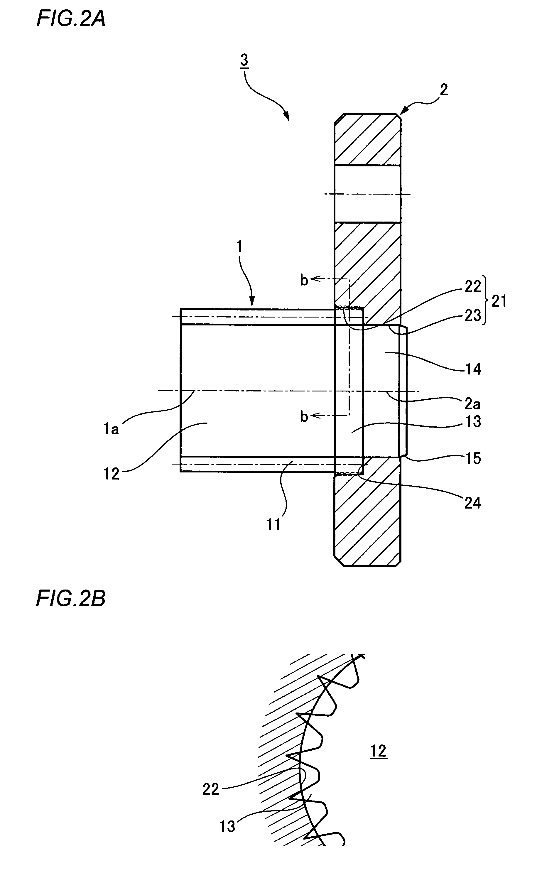
[0011]According to the present invention, only the press-fitting external teeth on the axial end portion of the gear are generated at a time of tooth cutting so that the addendum circle thereof is made larger and the tops thereof are shaped to be sharper in comparison with the external teeth of the gear. The press-fitting external tooth part is press-fitted into a press-fit bore of the counter-joint component, so that the tooth tops of the press-fitting external teeth cut into an inner circumference surface of the press-fit bore, and fastening strength between the gear and counter-joint component can be secured.
[0012]Furthermore, according to the present invention, the boss is protruded concentrically from the press-fitting external tooth part, and the press-fitting external tooth part is press-fitted into the press-fit bore while the boss is press-fitted into the boss press-fit bore formed in the counter-joint component. Thus, the two members can be fastened with sufficient strength in a manner that miss-alignment therebetween is avoided.

Problems solved by technology

However, in some cases, design-wise it is impossible to have a space for installing such a key, a knock pin, and so on.

Method used


Image

  • Method of fastening gear and structure of the same
  • Method of fastening gear and structure of the same
  • Method of fastening gear and structure of the same

Examples


Embodiment Construction

[0016]An example of a method of fastening a gear according to the present invention is described below with reference to the drawings.

[0017]FIG. 1 is an explanatory view that shows a method of fastening a gear of this embodiment, and FIG. 2 is an explanatory view showing the obtained gear fastening structure. With reference to FIG. 1, a reference numeral 1 denotes a gear that is, for example, a second-stage pinion of a double stage planetary gear device. A reference numeral 2 denotes a counter-joint component that is, for example, a first-stage planetary carrier of the double stage planetary gear device.

[0018]The second-stage pinion 1 has a pinion main part 12 formed with external teeth 11 having a prescribed addendum circle. The pinion main part 12 is formed with press-fitting external tooth part 13 adjacent to the external teeth 11. The press-fitting external tooth part 13 is formed on its circumferential outer surface with press-fitting external teeth 13a whose addendum circle is...


PUM

PropertyMeasurementUnit
diameteraaaaaaaaaa
lengthaaaaaaaaaa
widthaaaaaaaaaa

Abstract

In a fastening method of press-fitting and fixing an axial end section of a second-stage pinion (1) into a circular opening (21) of a first-stage planetary carrier (2), first press-fitting external teeth (13a), which have an addendum circle larger than an addendum circle of the other pinion part and has a sharp tooth top, are generated through manufacturing of tooth-cutting at an outer circumferential section of the axial end portion of the second-stage pinion (1). Then, a press-fit bore (22) that has a smaller diameter than the addendum circle of the press-fitting external teeth (13a), is formed at the circular opening (21) of the first-stage planetary carrier (2). The press-fitting external teeth (13a) are then press-fitted into the press-fit bore (22) so that tooth tops thereof cut into an inner circumference surface of the press-fit bore (22) to secure fastening strength between the second-stage pinion (1) and the first-stage planetary carrier (2).

Description

TECHNICAL FIELD[0001]The present invention relates to a method of fastening a gear and a structure of fastening the gear, whereby a boss of a gear can be surely fastened into a circular opening of a counter-joint component without using a key, a knock pin, and so on.BACKGROUND ART[0002]A gear is generally fastened to a counter-joint component by press-fitting wherein a small-diameter boss formed at an axial end of the gear is press-fitted into a circular opening for press-fit which is formed in the counter-joint component. Such a method is disclosed in JP 8-247223 A, for example. When great fastening strength is required, for example as in a case where a gear is concentrically fastened to a rotational output shaft, a key, a knock pin, and so forth are used for securing enough fastening strength of the gear.[0003]However, in some cases, design-wise it is impossible to have a space for installing such a key, a knock pin, and so on.DISCLOSURE OF INVENTION[0004]An object of the present ...

Claims


Application Information

Patent Timeline
Patent Type & Authority Patents(United States)
IPC IPC(8): B21D53/28F16H55/17
CPCF16D1/072F16H57/0025F16H55/17Y10T29/49464Y10T29/49934Y10T29/49462Y10T29/49465F16H57/082
Inventor SHIROKOSHI, NORIO
Owner HARMONIC DRIVE SYST IND CO LTD
Learn More