
Method and device for an overload detection in hand-guided power tools

a technology overload detection, which is applied in the direction of emergency protective arrangements responsive to undesired changes, motor/generator/converter stoppers, and dynamo-electric converter control, etc. it can solve the problem of thermal failure of one or more components of hand-guided power tools, high current flow, and high strain on the motor that it comes to a standstill. , to achieve the effect of preventing thermal overload and reducing the operation curren

Inactive Publication Date: 2011-09-13
ROBERT BOSCH GMBH
View PDF17 Cites 24 Cited by
  • Summary
  • Abstract
  • Description
  • Claims
  • Application Information

AI Technical Summary

Benefits of technology

Effectively detects thermal overload in critical components before damage occurs, allowing for efficient prevention of thermal failures while using cost-effective and minimally invasive components, and tolerating temporary power surges to avoid premature switching-off.

Problems solved by technology

In power tools, situations can arise in which so much strain is placed on the motor that it comes to a standstill.
When at a standstill, though, the electric motor continues to present only a very low ohmic resistance in relation to the energy source, resulting in very powerful flows of current.
If there is no reaction to this state, for example by switching off the power, this can lead within seconds to a thermal failure of one or more components of the hand-guided power tool, for example a connecting line, the electric motor, or solder connections.
Such a failure can also occur when the jamming occurs several times in succession without sufficient cool-down phases being observed between them.
Typically in battery-powered hand-guided power tools, the thermal durability is increased through the use of high-temperature-resistant, low-ohm components, but this only delays the time at which the thermal failure eventually occurs.
The components required for this, however, are expensive and can hamper the performance of the hand-guided power tool.
The presetting of fixed current limits, however, also triggers a switching-off of the hand-guided power tool with the occurrence of temporary power surges, even though the tool would have been able to withstand them.
The disadvantage of this method, however, is that due to a low thermal conductivity or a volumetric expansion of the critical components, there can be a delay between the reaching of a critical temperature and the detection of this critical temperature.

Method used


Image

  • Method and device for an overload detection in hand-guided power tools
  • Method and device for an overload detection in hand-guided power tools

Examples


Embodiment Construction

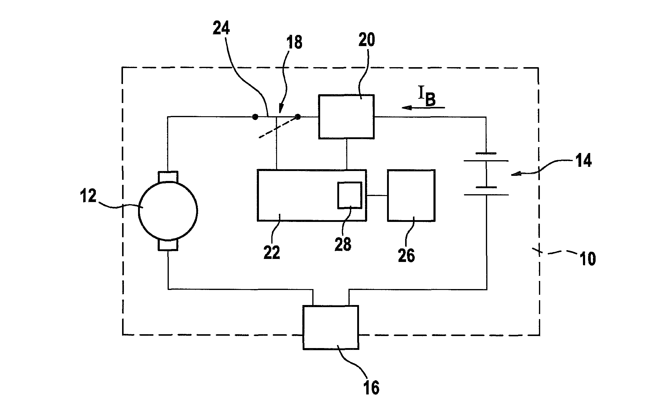
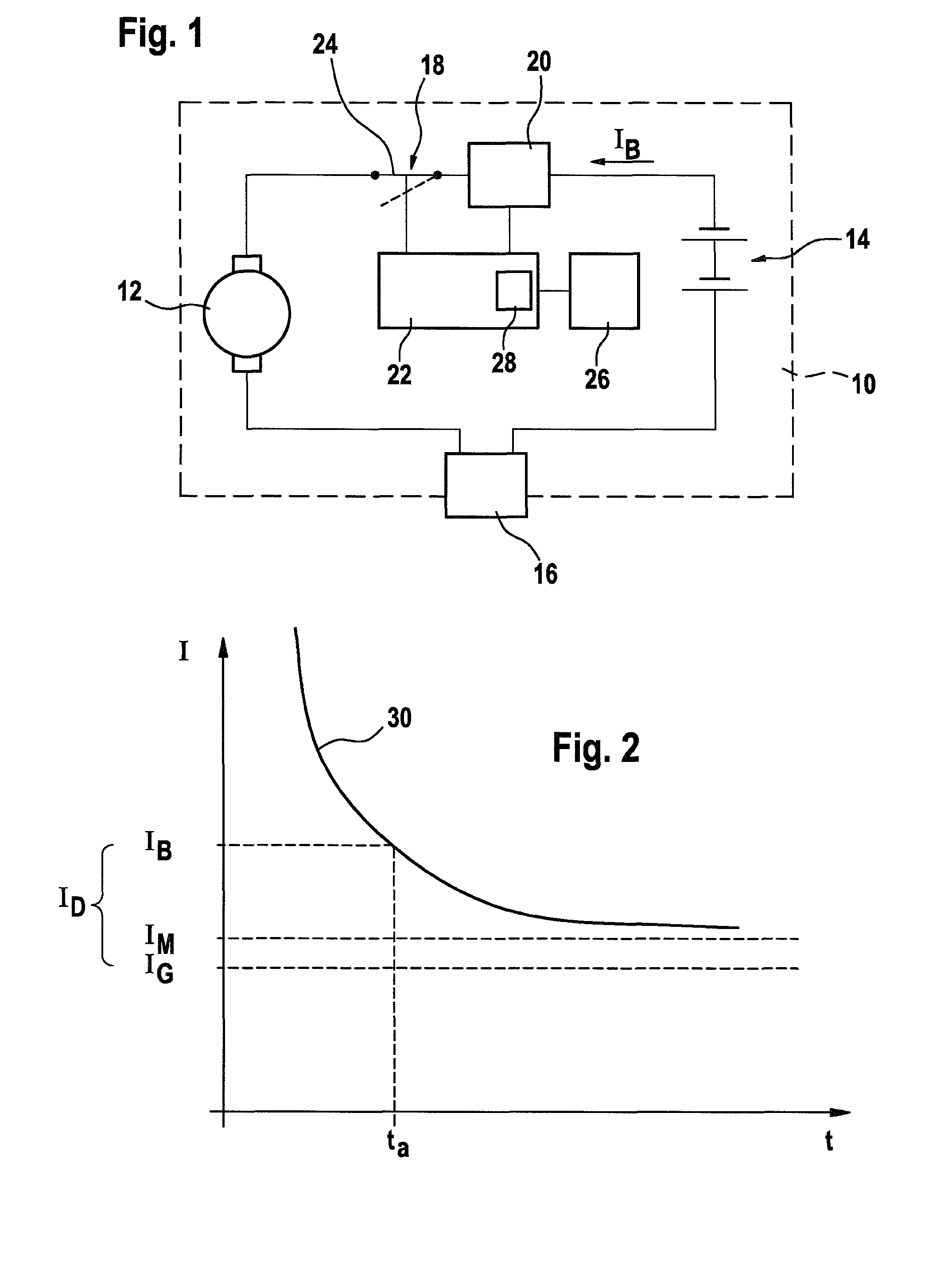
[0023]FIG. 1 shows a hand-guided power tool 10 equipped with an electric motor 12; the hand-guided power tool 10 is powered by a rechargeable battery pack 14. Starting from the battery pack 14, the circuit includes a control 16, the electric motor 12, a circuit breaking device 18, and a current measuring device 20. A monitoring device 22 triggers the circuit breaking device 18. The circuit breaking device 18 has a switch 24 (which can also be embodied in the form of a semiconductor component), which as a rule is closed, but can be opened as needed by the monitoring device 22. The open position of the switch 24 is depicted with dashed lines. Finally, the battery pack 14 is associated with a temperature measuring device 26 that detects the temperature of the battery pack 14. At least one current value is stored in the monitoring device 22, in this case being permanently stored in the hardware.

[0024]At the moment that the hand-guided power tool 10 is switched on, the above-mentioned su...


PUM


Abstract

The invention relates to a method for detecting an overload in an electric hand tool (10) comprising an electric motor (12), in particular a battery-driven electric hand tool (10). According to the invention, an operating current (iB) of the electric motor (12) is determined, the difference (ID) between the value of the operating current (IB) and at least one stored current value (IG) is determined and a thermal overload of the electric hand tool (10) is deduced from said difference (ID). The invention also relates to a corresponding monitoring device (22).

Description

CROSS-REFERENCE TO RELATED APPLICATIONS[0001]The invention described and claimed hereinbelow is also described in German Patent Application DE 10 2005 038 225.8 filed on Aug. 12, 2005. This German Patent Application, whose subject matter is incorporated here by reference, provides the basis for a claim of priority of invention under 35 U.S.C. 119(a)-(d).BACKGROUND OF THE INVENTION[0002]The invention relates to a method for detecting an overload situation in a hand-guided power tool equipped with an electric motor, and to a corresponding device.[0003]Methods for detecting an overload situation in a hand-guided power tool equipped with an electric motor are known from the prior art. The term “hand-guided power tool” is understood to mean, for example, screwdrivers, drill / drivers, circular saws, jigsaws, power planers, rotary hammers, or impact drills. In addition to hand-guided power tools that are driven by line current, there are also hand-guided power tools powered by rechargeable ...

Claims


Application Information

Patent Timeline
Patent Type & Authority Patents(United States)
IPC IPC(8): H02P1/00
CPCB25F5/001H02H6/005H02H7/18
Inventor ROEHM, HEIKOHIRSCHBURGER, WOLFGANG
Owner ROBERT BOSCH GMBH
Learn More