Electrodipping device

Active Publication Date: 2011-09-13
EISENMANN AG
View PDF5 Cites 0 Cited by
  • Summary
  • Abstract
  • Description
  • Claims
  • Application Information

AI Technical Summary

Benefits of technology

[0014]The object of the present invention is to configure an electro-dip lacquering device of the type named at the beginning in such a way that it can be controlled more easily, is flexible, and causes less wear on the contact devices.
[0020]According to the invention, therefore, the division of the contact rail into sections, which is associated with rail cuts, is dispensed with and a galvanically continuous contact rail is used. In order now to be able to apply different potentials, and even potentials that change in the course of the movement, to the various workpieces, which all draw their voltage from the same contact rail, a separate voltage adjusting unit is assigned to each workpiece. This is activated according to the position of the workpiece such that the workpiece is always at the desired potential. In this way a very much more sensitive adjustment of the potentials at the workpieces can be accomplished than in the case of the known division of the contact rail into individual sections. A changeover to a different type of workpieces is possible without any problems solely by means of programming measures. The absence of cuts in the contact rail has a favourable effect on the lifetime of the contact devices.
[0023]In a particularly preferred embodiment of the invention, the position indicating device has a position code rail as well as a reading head for each workpiece, which head is moved together with the workpiece and is able to read the local code of the position code rail. Position code rails suitable for this are obtainable relatively cheaply in the trade and have a high level of accuracy.

Problems solved by technology

A reason for this measure inter alia is that the lacquer coating building up represents an electrical resistance, which makes the further build-up of the lacquer coating difficult.
The problem thus arises of how the voltage can be changed for each workpiece as it passes through the lacquer bath.
It is disadvantageous in this case that it is relatively difficult to track the path of each individual workpiece along the various sections of the contact rail in control terms and to effect the transition of the workpiece from one section to another section without “jump” in potential.
After all, the “cuts” in the contact rails which cause the galvanic separation also represent unevennesses in the contact rail which lead to wear of the contact devices that are moved together with the workpieces.

Method used


Image

  • Electrodipping device
  • Electrodipping device

Examples


Embodiment Construction

[0029]While this invention is susceptible of embodiment in many different forms, there is shown in the drawings and will herein be described in detail one or more embodiments with the understanding that the present disclosure is to be considered as an exemplification of the principles of the invention and is not intended to limit the invention to the embodiments illustrated.

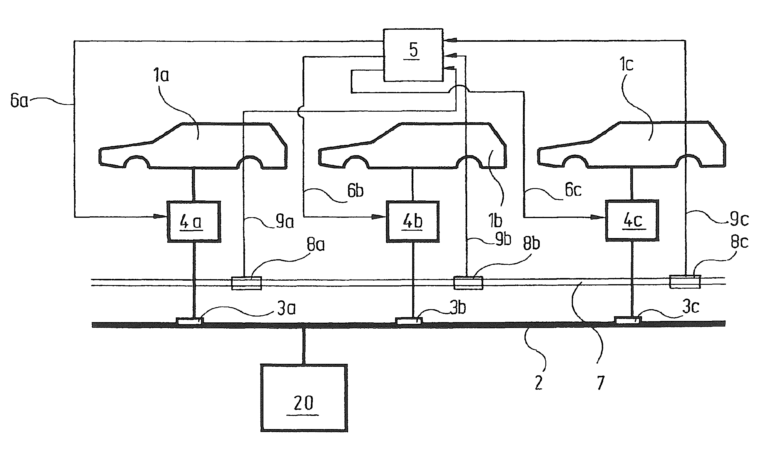
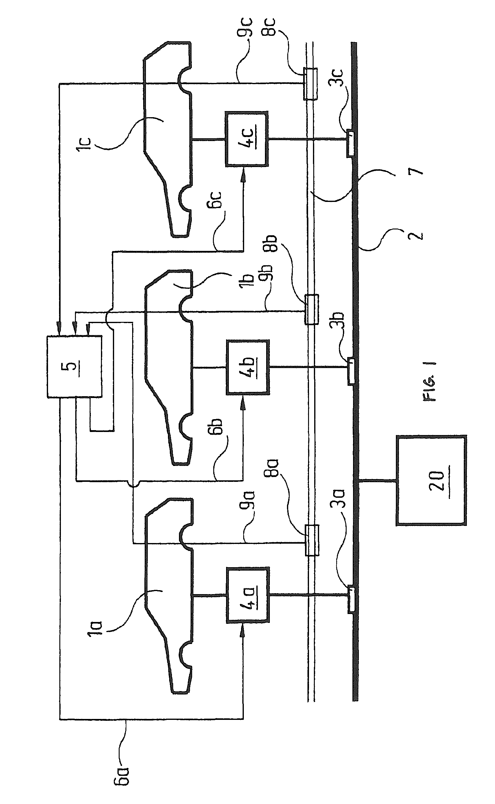
[0030]An embodiment of the invention is explained in greater detail below with reference to the drawing; the single FIGURE shows schematically the voltage supply of vehicle bodies in an electro-dip lacquering bath.

[0031]The drawing shows three vehicle bodies 1a, 1b, 1c in all, which can be thought of as dipped into a lacquer pool filled with lacquering liquid, as described in DE 199 42 556 C2 already mentioned above. The lacquer pool is not shown in FIG. 1, nor is the conveying device with which the various vehicle bodies 1a, 1b, 1c are moved continuously or intermittently through the lacquer pool. A suspension c...


PUM

PropertyMeasurementUnit
Electric potential / voltageaaaaaaaaaa
Distanceaaaaaaaaaa
Velocityaaaaaaaaaa

Abstract

The invention relates to an electrodipping device comprising, in a known manner, a bath of enamel, and a transport device used, during the continuous method, to dip the workpieces to be coated into the bath of enamel, to move the workpieces through the bath, and remove the same therefrom. Electrodes are arranged in the bath of enamel, along the path of displacement of the workpieces, said electrodes being connected to a voltage source with one pole thereof. The second pole of said voltage source is connected to a contact rail extending along the path of displacement of the workpieces. Each workpiece is provided with a contact device which is in contact with the contact rail. A controllable voltage regulating unit is arranged between each contact device and the corresponding workpiece. A position determination device enables the momentaneous position of each workpiece to be determined. A control system is used to apply a control signal to the corresponding voltage regulating unit in such a way as to maintain each workpiece at a desired voltage in each position of the course thereof through the bath of enamel.

Description

RELATED APPLICATIONS[0001]This application claims the filing benefit of International Patent Application No. PCT / EP2006 / 007561, filed Jul. 31, 2006, which claims the filing benefit of Germany Patent Application No. 10 2005 034 174.4 filed Aug. 5, 2005, the contents of which are incorporated herein by reference.TECHNICAL FIELD[0002]The invention relates to an electro-dip lacquering device with[0003]a) a lacquer bath;[0004]b) a conveying device, with which the workpieces to be lacquered can be dipped in a continuous operation into the lacquer bath, moved through this and lifted out again;[0005]c) a voltage source;[0006]d) electrodes arranged in the lacquer bath along the movement path of the workpieces, which electrodes are connected to a first pole of the voltage source;[0007]e) a contact rail, which extends along the movement path of the workpieces and is connected to the second pole of the voltage source;[0008]f) a contact device, which is in contact with the contact rail, for each...

Claims


Application Information

Patent Timeline
IPC IPC(8): C25D17/08
CPCC25D13/22
Inventor NOLLER, THOMAS
Owner EISENMANN AG
Why Eureka
Try Eureka