
Liquid droplet plug and spray system

a technology of liquid droplet and spray system, which is applied in the direction of inhalator, insect catcher and killer, other medical devices, etc., can solve the problems of loss of liquid, inability to allow for controlled vapour dispersion, and inconvenient use, and achieves convenient exchange of reservoirs, simple and efficient systems

Inactive Publication Date: 2011-09-13
APTAR FRANCE SAS
View PDF21 Cites 27 Cited by
  • Summary
  • Abstract
  • Description
  • Claims
  • Application Information

AI Technical Summary

Benefits of technology

The present invention is about a liquid droplet spray system that is efficient, simple, and inexpensive. The system has a modular design that allows for easy replacement of the reservoir and nozzle body without any spill or wastage of liquid. The system includes a disposable part and a permanent, non-disposable part, with the disposable part containing the reservoir, nozzle body, and a fluidic channel linking the reservoir to the nozzle body. The system also has a valve that ensures the disposable part is liquid tight even when removed from the system.

Problems solved by technology

Of course, air fresheners use strong fragrances so that this is not very pleasant.
Further, this leads to a loss of liquid if one forgets to put the cover back on, and it is impossible to allow for a controlled dispersion of the vapour amount.
Thus, when changing the reservoir, it would appear impossible to do such without any liquid spilling out.
Further, due to the design of the system, liquid may leak through the perforated membrane even when the system is not in use thus leading to wastage and related inconveniences such as unwanted fragrancing.
Of course, controlled dispensing is not possible either with this system.
The disadvantage is that this additional atomising duration will sometimes be either too long or too short and that a fixed time will not work with liquids of various viscosities and surface tensions and ambient conditions.
Although this device overcomes many of the above-raised inconveniences due to partly disposable items, it suffers from contamination of the space of the droplet spray device, which may in certain cases not be fully emptied after use.
A re-fill with another liquid substance will thus result in uncontrolled release, either in quantity or in actual substance caused by contamination.
Further, due to the presence of any remaining liquid substance, clogging may occur of the fluidic channel, of nozzles in the nozzle body or even of the reservoir thus impeaching the operation of the device.

Method used


Image

  • Liquid droplet plug and spray system
  • Liquid droplet plug and spray system
  • Liquid droplet plug and spray system

Examples


Embodiment Construction

[0032]An example of a preferred embodiment will now be described.

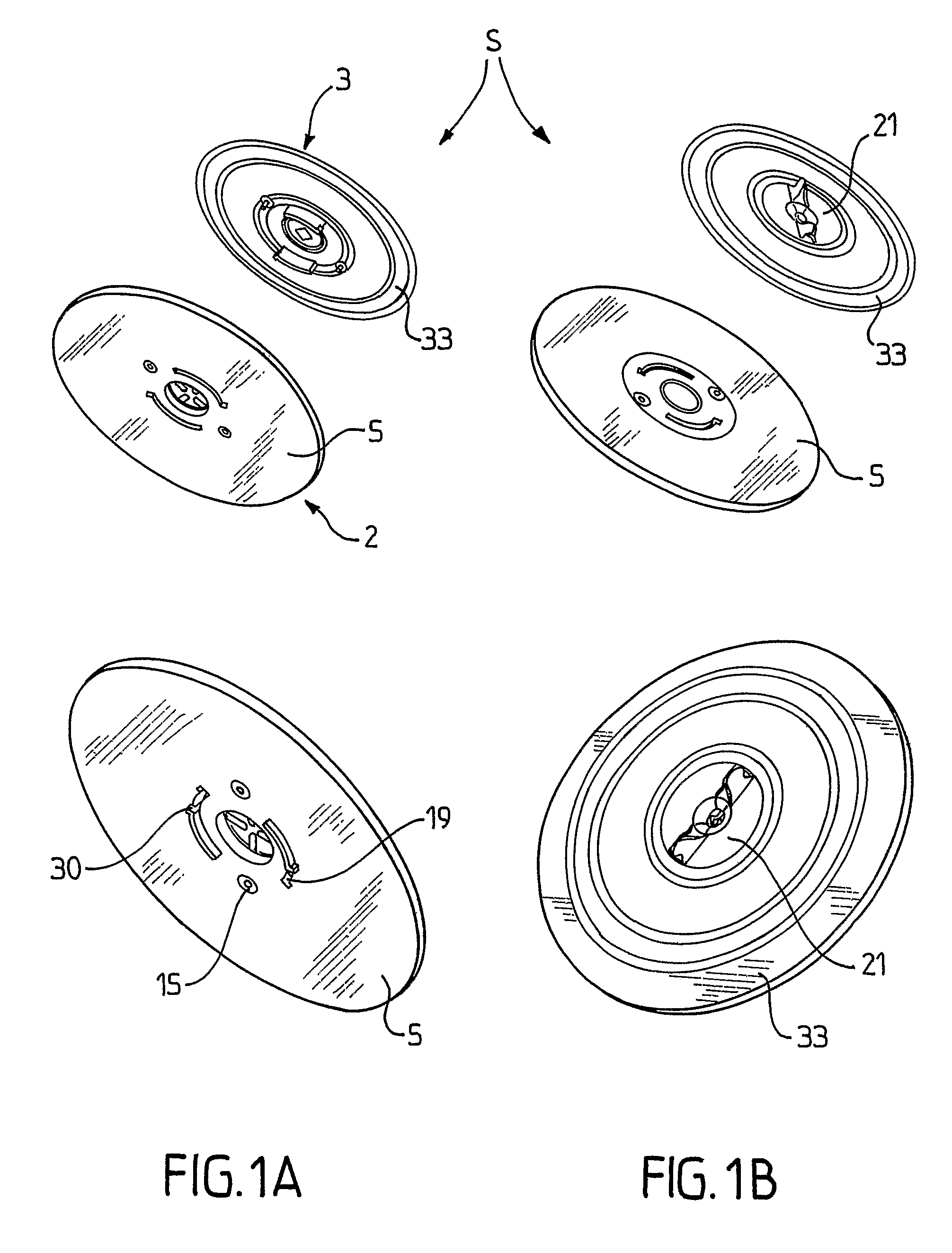
[0033]FIG. 1 shows a liquid droplet plug and spray system indicated by general reference S. This system contains a permanent, non-disposable part, and a disposable part. FIGS. 1a and 1b respectively show from below and from above a pre-assembly and a post-assembly view of the system.

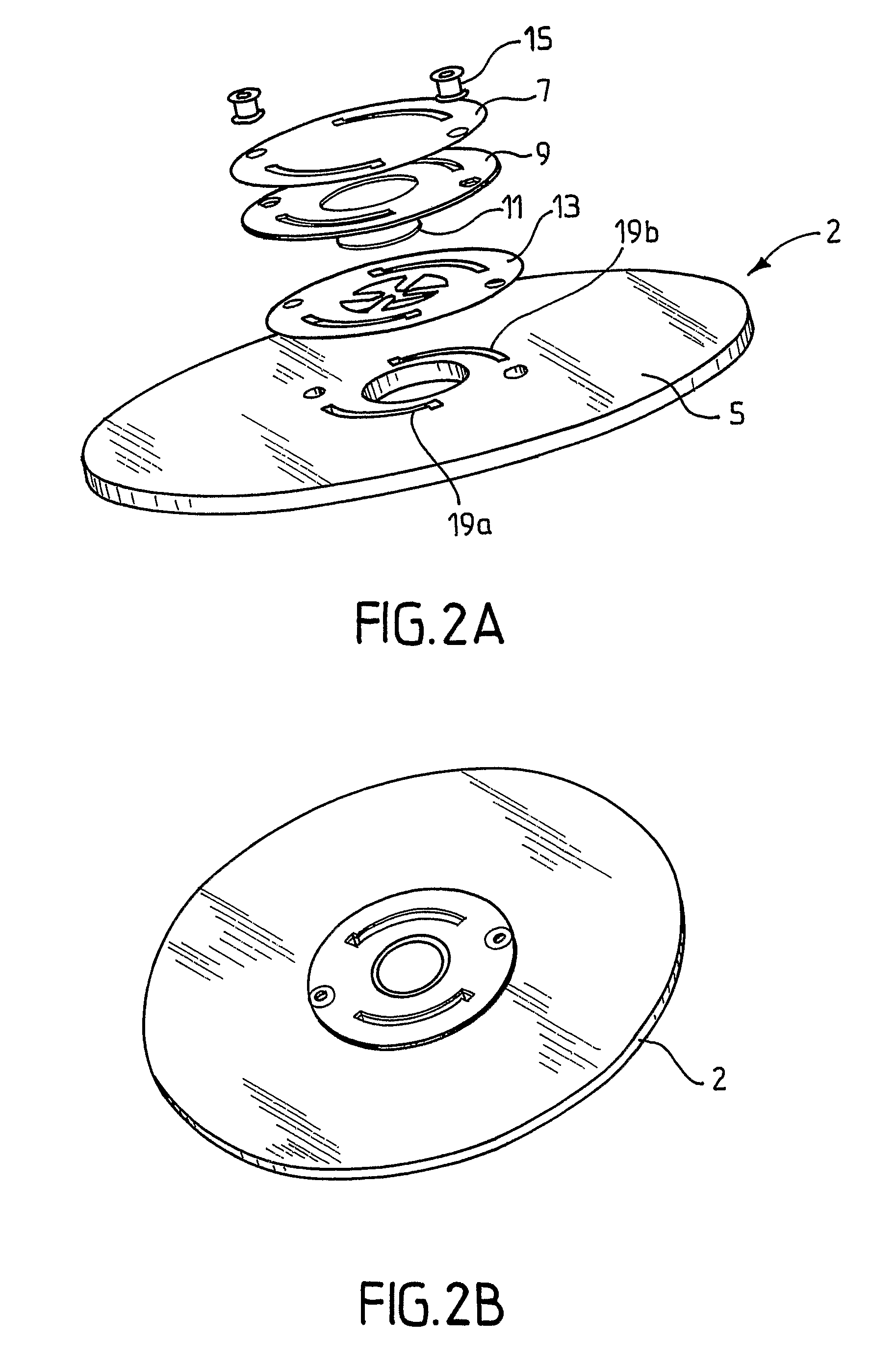
[0034]The permanent part comprises a support which may be a flexible electric circuit board or a PCB element, a membrane actuator, an insulator, an electromechanical actuator such as a piezoelectric element and an electrode. FIGS. 2a and 2b, respectively show an exploded view and an assembled view of an example of a disk-shaped permanent part, indicated by reference numeral 2, comprising a disk-shaped PCB 5, an electrode 13, a piezoelectric element 11, an insulator 9, and a membrane actuator 7, assembled one to the other by way of fastening means, here by way of rivets 15, to form a disk as shown in the assembled view in FIG. 2b. Of course ...


PUM

PropertyMeasurementUnit
poweraaaaaaaaaa
flexibleaaaaaaaaaa
pressureaaaaaaaaaa

Abstract

The present invention concerns a liquid droplet spray system for atomizing a liquid substance, comprising: a support having a central aperture (27), a liquid droplet spray device in which a space is provided, the space being arranged to receive the liquid substance, and including a nozzle body (28) covering the space such that the liquid substance may exit the space of the device by traversing the nozzle body (28) and the system by traversing the central aperture (27) of the support, a reservoir (33) for containing the liquid substance.

Description

[0001]This is a National Phase Application in the United States of International Patent Application No. PCT / EP2005 / 006089 filed Jun. 7, 2005, which claims priority on European Patent Application No. 04013559.2, filed Jun. 9, 2004. The entire disclosures of the above patent applications are hereby incorporated by reference.FIELD OF THE INVENTION[0002]The present invention relates to a liquid droplet plug & spray system comprising a liquid droplet spray device suitable for atomising a liquid substance, such as a personal or an ambient fragrance or a functional liquid such as an insecticide or a medicated liquid. Such a device may be used, e.g., for fragrance or functional or medical liquid dispensers, for an inhaler or the like, for controlled release of droplets of such. More specifically, the present invention concerns a liquid droplet spray system which is of modular design having a disposable part and a permanent, nondisposable part.BACKGROUND OF THE INVENTION[0003]Various devices...

Claims


Application Information

Patent Timeline
Patent Type & Authority Patents(United States)
IPC IPC(8): B05B1/08B05B9/03B05B1/30B05B1/00A61M11/06A01M1/20A61L9/14A61M11/00A61M15/00B05B7/14B05B7/24B05B9/08B05B12/14B05B15/02B05B15/55B05B17/00B05B17/06
CPCA01M1/2044A01M1/205A61L9/14A61M11/005A61M15/0085B05B7/2472B05B12/1409B05B15/025B05B17/0638B05B17/0676A61M15/0003A61M15/0048A61M15/0028A61M2202/04A61M2202/064A61M2205/123A61M2205/128A61M2205/8206B05B7/1481B05B9/08B05B12/1472B05B15/55
Inventor HESS, JOSEPHFERIANI, AMIRLUGINBUHL, PHILIPPEWEBER, RAPHAEL
Owner APTAR FRANCE SAS
Learn More