Arrangement for generating extreme ultraviolet radiation by means of an electrically operated gas discharge

a gas discharge and electric discharge technology, which is applied in the direction of electric discharge lamps, lasers, manufacturing tools, etc., can solve the problems of unstable plasma generation, insufficient life of electrodes formed in this way, and the difficulty of adjusting the desired layer thickness of applied materials, etc., to achieve better protection, improve the rotational speed of electrodes, and improve the effect of layer thickness adjustmen

Inactive Publication Date: 2011-08-30
USHIO DENKI KK
View PDF7 Cites 0 Cited by
  • Summary
  • Abstract
  • Description
  • Claims
  • Application Information

AI Technical Summary

Benefits of technology

[0010]Therefore, it is the object of the invention to achieve an improvement in the adjustment of the layer thickness when applying a molten metal to the electrode surfaces and to provide better protection against the uncontrolled spreading of molten metal into the environment that is associated with an increase in the rotational speed of the electrodes. In particular, it should be possible to increase the rotational speed to the extent that unconsumed discharge zones of the electrodes are always situated in the discharge area at repetition frequencies of several kilohertz.
[0015]In order to prevent electrical short circuiting it is advantageous when a disk-shaped insulating body is provided in the electrode area provided for applying the molten metal, and the insulating body dips into the intermediate space between the two electrodes. In this construction, the liquid dispensing nozzles which are directed to the electrode surfaces of the two electrodes can be guided through the disk-shaped insulating body from opposite sides.
[0017]A pre-ionization of the emitter material is advantageous for the ignition of the plasma, particularly the evaporation of a droplet of advantageous emitter material injected between the electrodes.
[0021]The application of the molten metal according to the invention also has a particularly advantageous effect because the two rotating electrodes can contact the discharge circuit with a particularly low inductance owing to their horizontal arrangement.

Problems solved by technology

Studies carried out on a large number of electrode shapes for gas discharge sources such as Z-pinch electrodes, hollow-cathode electrodes, plasma focus electrodes or star pinch electrodes have shown that the lifetime of electrodes formed in this way is not sufficient for EUV projection lithography.
This technique is disadvantageous especially in that a desired layer thickness of the applied material can be adjusted only with difficulty.
On the other hand, when the rotational speed is too low, unconsumed portions of electrodes are too slowly brought into the discharge area and cause instability in the plasma generation.
This problem is particularly severe when applications require repetition rates of several kilohertz.

Method used


Image

  • Arrangement for generating extreme ultraviolet radiation by means of an electrically operated gas discharge
  • Arrangement for generating extreme ultraviolet radiation by means of an electrically operated gas discharge
  • Arrangement for generating extreme ultraviolet radiation by means of an electrically operated gas discharge

Examples


Embodiment Construction

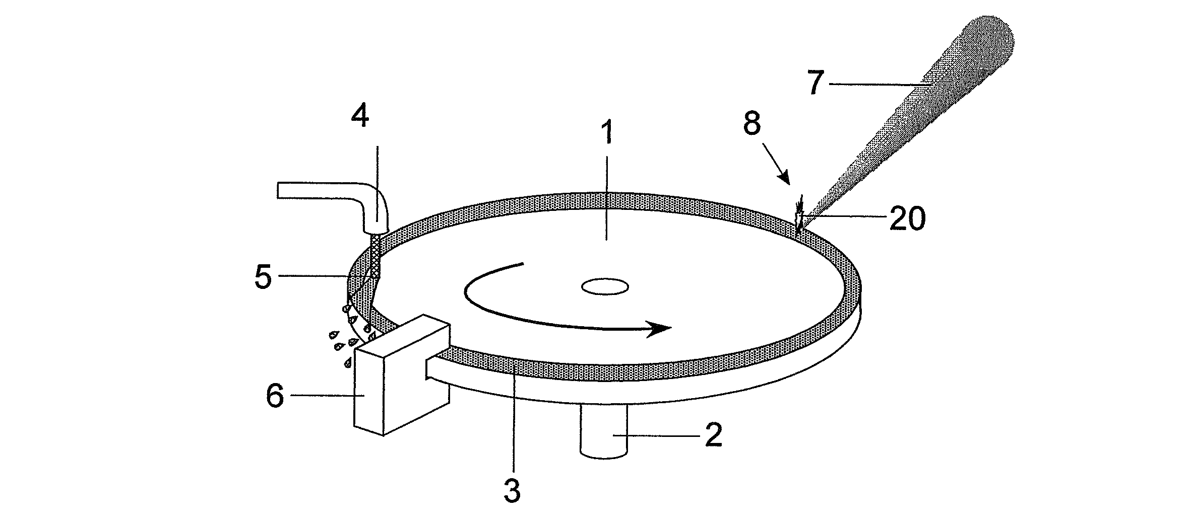
[0031]In FIG. 1 which illustrates the principle of the invention, a disk-shaped electrode 1 is rigidly connected to a rotatable shaft 2 in such a way that the center axis of symmetry of the electrode coincides with the axis of rotation R-R. An edge track running around the circumference of the electrode surface serves as a receiving area 3 for a molten metal, e.g., tin or a tin alloy, and is constructed so as to be wetting for this material. Wetting surfaces for the edge track can comprise, e.g., copper, chromium, nickel or gold.

[0032]The rest of the electrode surface, or at least a portion of the electrode surface adjoining the receiving area, should not be wetting for the emitter material because application of the molten metal is not desired here. Suitable non-wetting surfaces can comprise, e.g., PTFE, stainless steel, glass, or ceramic.

[0033]A liquid dispensing nozzle 4 of a fluid generator is directed to the receiving area 3 to apply the molten metal to the receiving area 3 in ...


PUM

PropertyMeasurementUnit
diameteraaaaaaaaaa
diameteraaaaaaaaaa
areaaaaaaaaaaa

Abstract

An arrangement for generating extreme ultraviolet radiation by an electrically operated gas discharge which achieves an improvement in the adjustment of the layer thickness when applying a molten metal to the electrode surfaces and provides better protection against the uncontrolled spreading of molten metal into the environment that is associated with an increase in the rotational speed of the electrodes. It should be possible to increase the rotational speed to the extent that unconsumed discharge zones of the electrodes are always situated in the discharge area at repetition frequencies of several kilohertz. An edge area to be covered has at least one receiving area which extends circumferentially in a closed manner along the edge of the electrode on the electrode surface and which is constructed so as to be wetting for the molten metal and to which a liquid dispensing nozzle is directed for regenerative application of the molten metal.

Description

CROSS-REFERENCE TO RELATED APPLICATION[0001]This application claims priority of German Application No. 10 2006 015 641.2, filed Mar. 31, 2006, the complete disclosure of which is hereby incorporated by reference.BACKGROUND OF THE INVENTION[0002]a) Field of the Invention[0003]The invention is directed to an arrangement for generating extreme ultraviolet radiation by means of an electrically operated gas discharge with a discharge chamber which has a discharge area for a gas discharge for forming a plasma that emits the radiation, a first disk-shaped electrode and a second disk-shaped electrode, at least one of which electrodes is mounted so as to be rotatable, an edge area to be covered by a molten metal, an energy beam source for providing a pre-ionization beam, and a discharge circuit connected to the electrodes for generating high-voltage pulses.[0004]b) Description of the Related Art[0005]Studies carried out on a large number of electrode shapes for gas discharge sources such as ...

Claims


Application Information

Patent Timeline
Patent Type & Authority Patents(United States)
IPC IPC(8): B23K15/00H05B31/26
CPCH05G2/003H05G2/005
Inventor HERGENHAN, GUIDOZIENER, CHRISTIAN
Owner USHIO DENKI KK
Why Eureka
Try Eureka