
Constructive arrangement in an umbilical cable and a process for the manufacture thereof

a construction arrangement and umbilical cable technology, applied in the direction of power cables, conductors, electrical equipment, etc., can solve the problems of excessive stiffness, time-consuming and expensive, and the inability of the bobbin used for temporary storage of triplex cables to hold the entire amount of material required to manufacture cables for deepwater use, etc., to reduce voltage and phase imbalance, modulation and voltage drop, and improve the electrical characteristics of the circuit

Active Publication Date: 2011-08-30
PRYSMIAN SURFLEX UMBILICAIS E TUBOS FLEXIVEIS DO BRASIL LTDA
View PDF3 Cites 7 Cited by
  • Summary
  • Abstract
  • Description
  • Claims
  • Application Information

AI Technical Summary

Benefits of technology

"The present invention provides a new arrangement for the conductors in a cable, which avoids the use of a triplex configuration. Instead, the conductors are grouped together and shielded individually, with separators used for positioning. The cross-section of the shield around each conductor is optimized for electrical performance. The conductors are all grouped together in a helical configuration, and the trefoils are positioned inside the cable using insulating fillers. This arrangement results in a more efficient and reliable cable design."

Problems solved by technology

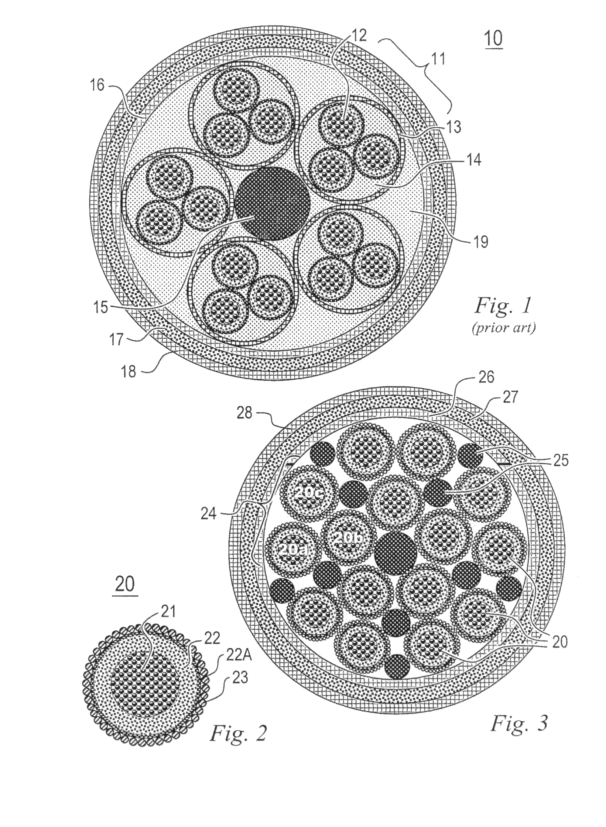
Furthermore, the bobbins used for temporary storage of the triplex cables 11 cannot hold the entire amount of material required to manufacture cables for deepwater use, which may be up to 12 kilometers long.
To achieve the high level of reliability required, special techniques are used in such splices, which are time-consuming and expensive.
Another disadvantage of the cable illustrated in FIG. 1 resides in its excessive stiffness, due in part to filling with thermoplastic material all its internal voids 14, 19, as well as the diameter of the cable, which in the cited example reaches 250 mm.
Such rigidity requires large-diameter bobbins to store the cable, rendering its transportation unwieldly.
Another problem consists in minimizing or even eliminating the intermediary splices required in the umbilical cables manufactured according to the known techniques.
One further problem consists in producing a cable that is more flexible than the known umbilical cables.
Still another problem consists in providing a manufacturing process less costly than those currently known, both in terms of financial cost and in terms of time expended.
Yet another problem consists in substantially improving the electrical characteristics of the circuits, i.e. reducing voltage and phase imbalance, modulation and voltage drops.

Method used


Image

  • Constructive arrangement in an umbilical cable and a process for the manufacture thereof
  • Constructive arrangement in an umbilical cable and a process for the manufacture thereof

Examples


Embodiment Construction

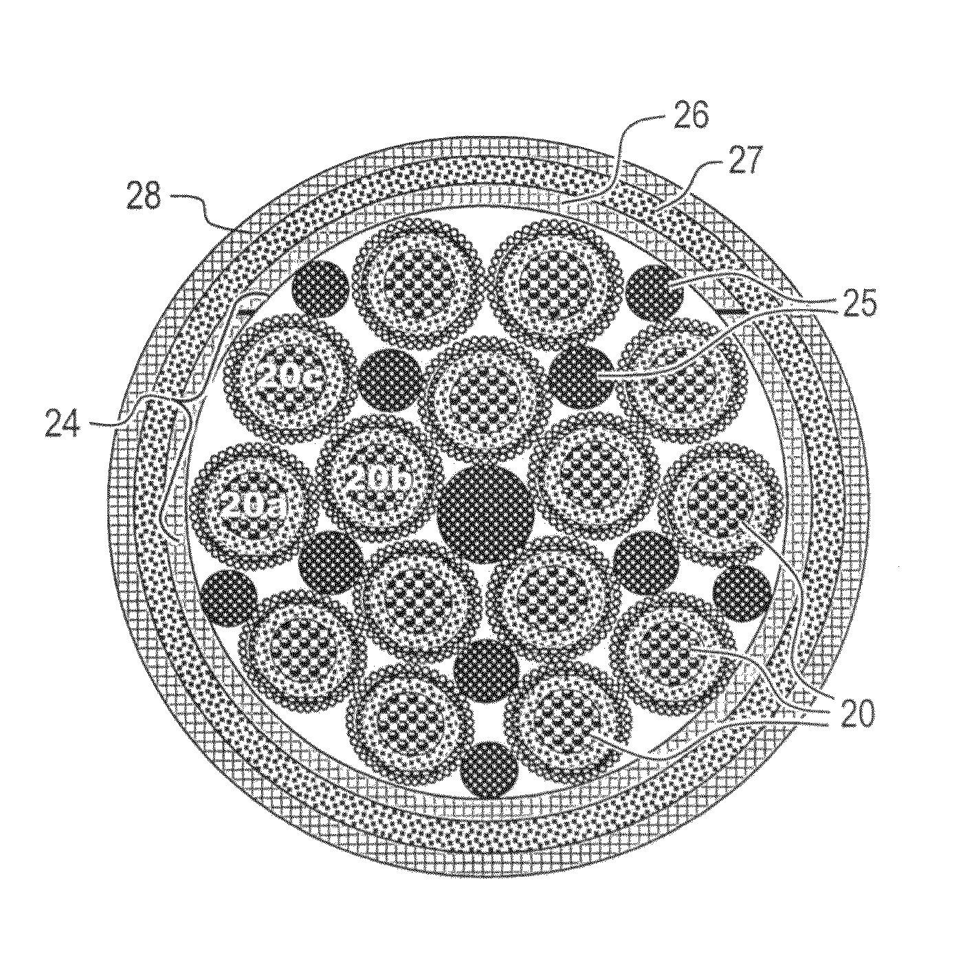
[0022]Referring now to FIG. 2, each of the conductors that will form the umbilical cable comprises a central core 21 of conductive metal, preferably of copper but not limited to this metal, surrounded by a sheath of insulating material 22, preferably covered with a semiconductor layer 22A, which is in turn surrounded by the conductors 23 of the metallic shielding, preferably comprised of copper but not limited to this metal. In the exemplary embodiment now described, the sheath 22 is made of a thermoplastic material, preferably polyethylene, applied over said central core by extrusion. However, other materials and techniques may be used to provide the insulating layer 22. The metallic shielding consists of a plurality of metal wires 23, contiguously disposed and in mutual contact, helically wound over the outer face of the insulating sheath 22. The sum of the cross-section areas of the shielding wires is that one which provides an optimizing of the electrical characteristics of the ...


PUM

PropertyMeasurementUnit
depthsaaaaaaaaaa
depthsaaaaaaaaaa
areaaaaaaaaaaa

Abstract

An umbilical cable, particularly adequate for subsea exploration, contains two or more three-phase power supply circuits, each consisting of three conductors grouped in a trefoil configuration, each conductor including a metal core surrounded by an insulating sheath, each conductor being provided with an individual shielding whose cross-section is less than, equal to or greater than that of the core. Advantageously, each insulating sheath may be surrounded by a layer of semiconductor material. Filler spacers made of an insulating material, preferably polyethylene, may be used to aid in the positioning of the trefoils. The cable provides an economy of material, an increased flexibility, a reduction of the diameter of the finished cable and a substantial decrease of manufacturing time as compared with cables produced in accordance with the known art. A manufacturing method for an umbilical cable is also disclosed.

Description

CROSS REFERENCE TO RELATED APPLICATION[0001]This application is a national phase application based on PCT / BR2006 / 000287, filed Dec. 21, 2006, the content of which is incorporated herein by reference.FIELD OF THE INVENTION[0002]The present invention refers to the field of electric power conductor cables, and refers more particularly to the cables used to supply electric power at medium and high voltages to heavy-duty equipments, such as, for example, the ones employed in subsea oil exploration.DESCRIPTION OF THE PRIOR ART[0003]The search for new oil reservoirs has led to the prospecting and exploration in the sea bed, not only in the continental shelf, but also in deeper waters. There are at present wells extending to depths in the order of 2 kilometers, whose operation requires the development of specific technologies, substantially different from those traditionally employed at water depths of less than 300 meters.[0004]One important aspect of such technologies is related to the ex...

Claims


Application Information

Patent Timeline
Patent Type & Authority Patents(United States)
IPC IPC(8): H01B9/02
CPCH01B7/0072H01B7/046
Inventor LIMA, ALOISIO JOSE DE OLLVEIRADO NASCIMENTO, ANTONIO PEREIRA FILHOFERREIRA, CARLOS ALBERTO GODINHO
Owner PRYSMIAN SURFLEX UMBILICAIS E TUBOS FLEXIVEIS DO BRASIL LTDA
Learn More